Operating Systems
Start Lecture #14
5.1.4: Direct Memory Access (DMA)
We now address the second question, moving data between the
controller and the main memory.
Recall that (independent of the issue with respect to DMA) the disk
controller, when processing a read request pulls the desired data
from the disk to its own buffer (and pushes data from the buffer to
the disk when processing a write).
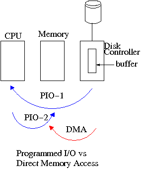
Without DMA, i.e., with programmed I/O (PIO), the
cpu then does loads and stores (assuming the controller buffer is
memory mapped, or uses I/O instructions if it is not) to copy the data
from the buffer to the desired memory locations.
A DMA controller, instead writes the main memory itself, without
intervention of the CPU.
Clearly DMA saves CPU work.
But this might not be important if the CPU is limited by the memory
or by system buses.
An important point is that there is less data movement with DMA so
the buses are used less and the entire operation takes less
time.
Compare the two blue arrows vs. the single red arrow.
Since PIO is pure software it is easier to change, which is an
advantage.
DMA does need a number of bus transfers from the CPU to the
controller to specify the DMA.
So DMA is most effective for large transfers where the setup is
amortized.
A serious conceptual difference with DMA is that the bus now has
multiple masters
and hence requires arbitration,
which leads to issues we faced with critical sections.
Why have the buffer?
Why not just go from the disk straight to the memory?
- Speed matching.
The disk supplies data at a fixed rate, which might exceed the
rate the memory can accept it.
In particular the memory might be busy servicing a request from
the processor or from another DMA controller.
Alternatively, the disk might supply data at a slower rate than
the memory (and memory bus) can handle thus under-utilizing an
important system resource.
- Error detection and correction.
The disk controller verifies the checksum written on the disk.
Homework: 12
5.1.5 Interrupts Revisited
Precise and Imprecise Interrupts
5.2 Principles of I/O Software
As with any large software system, good design and layering is
important.
5.2.1 Goals of the I/O Software
Device Independence
We want to have most of the OS to be unaware of the characteristics
of the specific devices attached to the system.
(This principle of device independence is not limited to I/O; we
also want the OS to be largely unaware of the CPU type itself.)
This objective has been accomplished quite well for files stored on
various devices.
Most of the OS, including the file system code, and most
applications can read or write a file without knowing if the file is
stored on a floppy disk, an internal SATA hard disk, an external
USB SCSI disk, an external USB Flash Ram, a tape, or (for reading) a
CD-ROM.
This principle also applies for user programs reading or writing
streams.
A program reading from ``standard input'', which is normally the
user's keyboard can be told to instead read from a disk file with no
change to the application program.
Similarly, ``standard output'' can be redirected to a disk file.
However, the low-level OS code dealing with disks is rather different
from that dealing keyboards and (character-oriented) terminals.
One can say that device independence permits programs to be
implemented as if they will read and write generic or abstract
devices, with the actual devices specified at run time.
Although writing to a disk has differences from writing to a
terminal, Unix cp, DOS copy, and
many programs we compose need not be aware of these differences.
However, there are devices that really are special.
The graphics interface to a monitor (that is, the graphics interface
presented by the video controller—often called a ``video
card'') does not resemble the ``stream of bytes'' we see for disk
files.
Homework:
What is device independence?
Uniform naming
We have already discussed the value of
the name space implemented by file systems.
There is no dependence between the name of the file and the device
on which it is stored.
So a file called IAmStoredOnAHardDisk might well be stored on a
floppy disk.
More interesting once a device is mounted on (Unix) directory, the
device is named exactly the same as the directory was.
So if a CD-ROM was mounted on (existing) directory /x/y, a file
named joe on the CD-ROM would now be accessible as /x/y/joe.
Error handling
There are several aspects to error handling including: detection,
correction (if possible) and reporting.
-
Detection should be done as close to where the error occurred
as possible before more damage is done (fault containment).
Moreover, the error may be obvious at the low level, but
harder to discover and classify if the erroneous data is
passed to higher level software.
-
Correction is sometimes easy, for example ECC memory does
this automatically (but the OS wants to know about the error
so that it can request replacement of the faulty chips before
unrecoverable double errors occur).
Other easy cases include successful retries for failed
ethernet transmissions.
In this example, while logging is appropriate, it is quite
reasonable for no action to be taken.
-
Error reporting tends to be awful.
The trouble is that the error occurs at a low level but by the
time it is reported the context is lost.
Creating the illusion of synchronous I/O
I/O must be asynchronous for good performance.
That is the OS cannot simply wait for an I/O to complete.
Instead, it proceeds with other activities and responds to the
interrupt that is generated when the I/O has finished.
Users (mostly) want no part of this.
The code sequence
    Read X
    Y = X+1
    Print Y
should print a value one greater than that read.
But if the assignment is performed before the read completes, the
wrong value can easily be printed.
Performance junkies sometimes do want the asynchrony so
that they can have another portion of their program executed while
the I/O is underway.
That is, they implement a mini-scheduler in their application
code.
See this message from linux kernel
developer Ingo Molnar for his take on asynchronous IO and
kernel/user threads/processes.
You can find the entire discussion
here.
Buffering
Buffering is often needed to hold data for examination prior to
sending it to its desired destination.
Since this involves copying the data, which can be expensive,
modern systems try to avoid as much buffering as possible.
This is especially noticeable in network transmissions, where the
data could conceivably be copied many times.
- From user space to kernel space as part of the write system
call.
- From kernel space to a kernel I/O buffer.
- From the I/O buffer to a buffer on the network adaptor.
- From the adapter on the source to the adapter on the destination.
- From the destination adapter to an I/O buffer.
- From the I/O buffer to kernel space.
- From kernel space to user space as part of the read system
call.
I am not sure if any systems actually do all seven.
Sharable vs. Dedicated Devices
For devices like printers and CD-ROM drives, only one user at a
time is permitted.
These are called serially reusable devices, which
we studied in the deadlocks chapter.
Devices such as disks and ethernet ports can, on the contrary, be
shared by concurrent processes without any deadlock risk.
5.2.2 Programmed I/O
As mentioned just above, with programmed I/O the
main processor (i.e., the one on which the OS runs) moves the data
between memory and the device.
This is the most straightforward method for performing I/O.
One question that arises is how does the processor know when the
device is ready to accept or supply new data.
In the simplest implementation, the processor, when it seeks to use
a device, loops continually querying the device status, until the
device reports that it is free.
This is called polling or
busy waiting.
    loop
        if device-available then exit loop
        do-useful-work
If we poll infrequently (and do useful work in between), there can
be a significant delay from when the previous I/O is complete to when
the OS detects the device availability.
If we poll frequently (and thus are able to do little useful work
in between) and the device is (sometimes) slow, polling is clearly
wasteful.
The extreme case is where the process does nothing between polls.
For a slow device this can take the CPU out of service for a
significant period.
This bad situation leads us to ... .
5.2.3 Interrupt-Driven (Programmed) I/O
As we have just seen, a difficulty with polling is determining the
frequency with which to poll.
Another problem is that the OS must continually return to the
polling loop, i.e., we must arrange that do-useful-work takes the
desired amount of time.
Really we want the device to tell the CPU when it is available,
which is exactly what an interrupt does.
The device interrupts the processor when it is ready and an
interrupt handler (a.k.a. an interrupt service routine) then
initiates transfer of the next datum.
Normally interrupt schemes perform better than polling, but not
always since
interrupts are expensive on modern machines.
To minimize interrupts, better controllers often employ ...
5.2.4 I/O Using DMA
We discussed DMA above.
An additional advantage of dma, not mentioned above, is that the
processor is interrupted only at the end of a command not after each
datum is transferred.
Many devices receive a character at a time, but with a dma
controller, an interrupt occurs only after a buffer has been
transferred.
5.3 I/O Software Layers
Layers of abstraction as usual prove to be effective.
Most systems are believed to use the following layers (but for many
systems, the OS code is not available for inspection).
- User-level I/O routines.
- Device-independent (kernel-level) I/O software.
- Device drivers.
- Interrupt handlers.
We will give a bottom up explanation.
5.3.1 Interrupt Handlers
We discussed the behavior of an interrupt handler
before when studying page faults.
Then it was called assembly-language code
.
A difference is that page faults are caused by specific user
instructions, whereas interrupts just occur
.
However, the assembly-language code
for a page fault
accomplishes essentially the same task as the interrupt handler does
for I/O.
In the present case, we have a process blocked on I/O and the I/O
event has just completed.
So the goal is to make the process ready and then call the
scheduler.
Possible methods are.
- Releasing a semaphore on which the process is waiting.
- Sending a message to the process.
- Inserting the process table entry onto the ready list.
Once the process is ready, it is up to the scheduler to decide when
it should run.
5.3.2 Device Drivers
Device drivers form the portion of the OS that is tailored to the
characteristics of individual controllers.
They form the dominant portion of the source code of the OS since
there are hundreds of drivers.
Normally some mechanism is used so that the only drivers loaded on a
given system are those corresponding to hardware actually present.
Indeed, modern systems often have loadable device drivers
,
which are loaded dynamically when needed.
This way if a user buys a new device, no changes to the operating
system are needed.
When the device is installed it will be detected during the boot
process and the corresponding driver is loaded.
Sometimes an even fancier method is used and the device can be
plugged in while the system is running (USB devices are like this).
In this case it is the device insertion that is detected by the OS
and that causes the driver to be loaded.
Some systems can dynamically unload a driver, when
the corresponding device is unplugged.
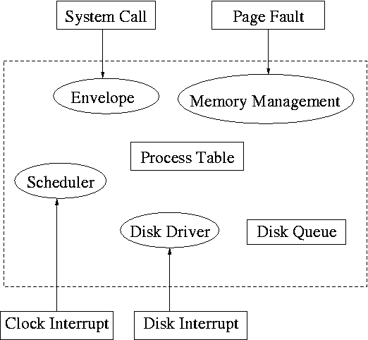
The driver has two parts
corresponding to its two access
points.
Recall the figure at the upper right, which we saw at the beginning
of the course.
- The driver is accessed by the main line OS via the envelope in
response to an I/O system call.
The portion of the driver accessed in this way is sometimes called
the
top
part.
- The driver is also accessed by the interrupt handler when the
I/O completes (this completion is signaled by an interrupt).
The portion of the driver accessed in this way is sometimes call
the
bottom
part.
In some system the drivers are implemented as user-mode processes.
Indeed, Tannenbaum's MINIX system works that way, and in previous
editions of the text, he describes such a scheme.
However, most systems have the drivers in the kernel itself and the
3e describes this scheme.
I previously included both descriptions, but have eliminated the
user-mode process description (actually I greyed it out).
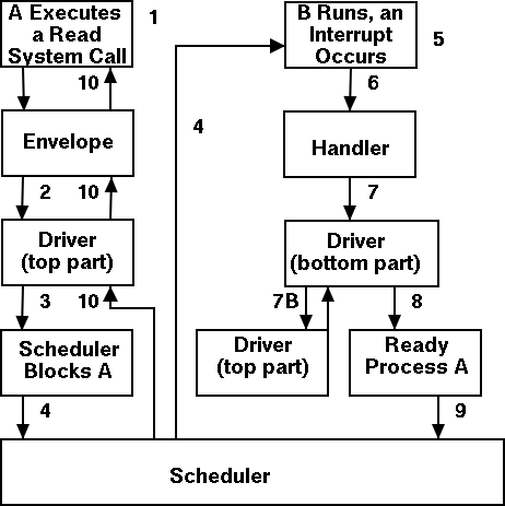
Driver in a self-service paradigm
The numbers in the diagram to the right correspond to the numbered
steps in the description that follows.
The bottom diagram shows the state of processes A and B at steps 1,
6, and 9 in the execution sequence described.
What follows is the Unix-like view in which the driver is invoked
by the OS acting in behalf of a user process (alternatively stated,
the process shifts into kernel mode).
Thus one says that the scheme follows a self-service
paradigm
in that the process itself (now in kernel mode) executes the driver.
- The user (A) issues an I/O system call.
- The main line, machine independent, OS prepares a
generic request for the driver and calls (the top part of)
the driver.
- If the driver was idle (i.e., the controller was idle), the
driver writes device registers on the controller ending with a
command for the controller to begin the actual I/O.
- If the controller was busy (doing work the driver gave it
previously), the driver simply queues the current request (the
driver dequeues this request below).
- The driver jumps to the scheduler indicating that the current
process should be blocked.
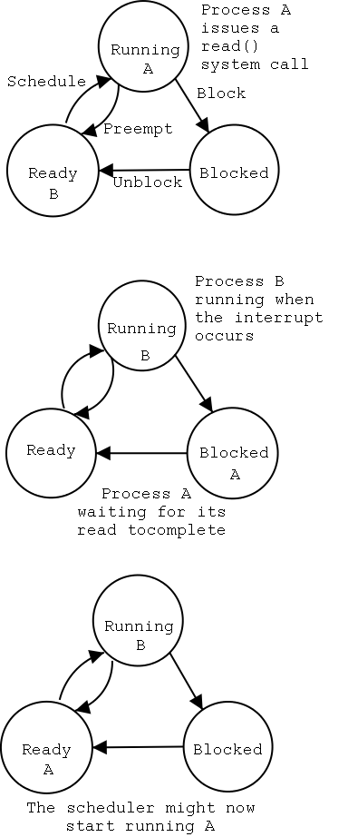
- The scheduler blocks A and runs (say) B.
- B starts running.
- An interrupt arrives (i.e., an I/O has been completed) and the
handler is invoked.
- The interrupt handler invokes (the bottom part of) the driver.
- The driver informs the main line perhaps passing data and
surely passing status (error, OK).
- The top part is called to start another I/O if the queue is
nonempty. We know the controller is free. Why?
Answer: We just received an interrupt saying so.
- The driver jumps to the scheduler indicating that process A should
be made ready.
- The scheduler picks a ready process to run. Assume it picks A.
- A resumes in the driver, which returns to the main line, which
returns to the user code.
Driver as a Process (Less Detailed Than Above)
Actions that occur when the user issues an I/O request.
- The main line OS prepares a generic request (e.g. read, not
read using Buslogic BT-958 SCSI controller) for the driver and
the driver is awakened.
Perhaps a message is sent to the driver to do both jobs.
- The driver wakes up.
- If the driver was idle (i.e., the controller is idle), the
driver writes device registers on the controller ending with a
command for the controller to begin the actual I/O.
- If the controller is busy (doing work the driver gave it), the
driver simply queues the current request (the driver dequeues this
below).
- The driver blocks waiting for an interrupt or for more
requests.
Actions that occur when an interrupt arrives (i.e., when an I/O has
been completed).
- The driver wakes up.
- The driver informs the main line perhaps passing data and
surely passing status (error, OK).
- The driver finds the next work item or blocks.
- If the queue of requests is non-empty, dequeue one and
proceed as if just received a request from the main line.
- If queue is empty, the driver blocks waiting for an
interrupt or a request from the main line.
5.3.3 Device-Independent I/O Software
The device-independent code cantains most of the I/O functionality,
but not most of the code since there are very many drivers.
All drivers of the same class (say all hard disk drivers) do
essentially the same thing in slightly different ways due to
slightly different controllers.
Uniform Interfacing for Device Drivers
As stated above the bulk of the OS code is made of device drivers
and thus it is important that the task of driver writing not be made
more difficult than needed.
As a result each class of devices (e.g. the class of all disks) has
a defined driver interface to which all drivers for that class of
device conform.
The device independent I/O portion processes user requests and calls
the drivers.
Naming is again an important O/S functionality.
In addition it offers a consistent interface to the drivers.
The Unix method works as follows
- Each device is associated with a
special
file in the
/dev directory.
- The i-nodes for these files contain an indication that these
are
special
files and also contain so called major and
minor device numbers.
- The major device number gives the number of the driver.
(These numbers are rather ad hoc, they correspond to the
position of the function pointer to the driver in a table of
function pointers.)
- The minor number indicates for which device (e.g., which scsi
cdrom drive) the request is intended.
- For example my system has two scsi disks (one is external via
USB, but that is not relevant).
The two disks are named by linux sda and sdb.
The partitions of sda are named sda1, sda2, etc.
From the following listing we can see that the scsi driver is
number 8 and that numbers are reserved for 15 partitions for
each scsi drive, which is the limit scsi supports.
The result is as follows.
        allan dev # ls -l /dev/sd*
        brw-r----- 1 root disk 8,  0 Apr 25 09:55 /dev/sda
        brw-r----- 1 root disk 8,  1 Apr 25 09:55 /dev/sda1
        brw-r----- 1 root disk 8,  2 Apr 25 09:55 /dev/sda2
        brw-r----- 1 root disk 8,  3 Apr 25 09:55 /dev/sda3
        brw-r----- 1 root disk 8,  4 Apr 25 09:55 /dev/sda4
        brw-r----- 1 root disk 8,  5 Apr 25 09:55 /dev/sda5
        brw-r----- 1 root disk 8,  6 Apr 25 09:55 /dev/sda6
        brw-r----- 1 root disk 8, 16 Apr 25 09:55 /dev/sdb
        brw-r----- 1 root disk 8, 17 Apr 25 09:55 /dev/sdb1
        brw-r----- 1 root disk 8, 18 Apr 25 09:55 /dev/sdb2
        brw-r----- 1 root disk 8, 19 Apr 25 09:55 /dev/sdb3
        brw-r----- 1 root disk 8, 20 Apr 25 09:55 /dev/sdb4
        allan dev #
Protection. A wide range of possibilities are
actually done in real systems.
Including both extreme examples of
everything is permitted and nothing is (directly) permitted.
- In ms-dos any process can write to any file.
Presumably, our offensive nuclear missile launchers never ran
dos.
- In IBM 360/370/390 mainframe OS's, normal processors do not
access devices.
Indeed the main CPU doesn't issue the I/O requests.
Instead an I/O channel is used and the mainline constructs a
channel program and tells the channel to invoke it.
- Unix uses normal rwx bits on files in /dev (I don't believe x
is used).
Buffering
Buffering is necessary since requests come in a size specified by
the user and data is delivered by reads and accepted by writes in a
size specified by the device.
It is also important so that a user process using getchar() is not
blocked and unblocked for each character read.
The text describes double buffering and circular buffers, which
are important programming techniques, but are not specific to
operating systems.
Error Reporting
Allocating and Releasing Dedicated Devices
The system must enforce exclusive access for
non-shared devices like CD-ROMs.
5.3.4 User-Space Software
A good deal of I/O software is actually executed by unprivileged
code running in user space.
This code includes library routines linked into user programs,
standard utilities, and daemon processes.
If one uses the strict definition that the operating system
consists of the (supervisor-mode) kernel, then this I/O code is not
part of the OS.
However, very few use this strict definition.
Library Routines
Some library routines are very simple and just move their arguments
into the correct place (e.g., a specific register) and then issue a
trap to the correct system call to do the real work.
I think everyone considers these routines to be part of the
operating system.
Indeed, they implement the published user interface to the OS.
For example, when we specify the (Unix) read system call by
count = read (fd, buffer, nbytes)
as we did in chapter 1, we are really
giving the parameters and accepting the return value of such a
library routine.
Although users could write these routines, it would make their
programs non-portable and would require them to write in assembly
language since neither trap nor specifying individual
registers is available in high-level languages.
Other library routines, notably standard I/O (stdio) in Unix, are
definitely not trivial.
For example consider the formatting of floating point numbers done
in printf and the reverse operation done in scanf.
In unix-like systems the graphics libraries and the gui itself are
outside the kernel.
Graphics libraries are quite large and complex.
In windows, the gui is inside the kernel.
Utilities and Daemons
Printing to a local printer is often performed in part by a regular
program (lpr in Unix) that copies (or links) the file to a standard
place, and in part by a daemon (lpd in Unix)
that reads the copied files and sends them to the printer.
The daemon might be started when the system boots.
Note that this implementation of printing
uses spooling, i.e., the file to be printed is
copied somewhere by lpr and then the daemon works with this copy.
Mail uses a similar technique (but generally it is called queuing,
not spooling).
5.3.A Summary
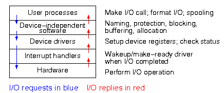
The diagram on the right shows the various layers and some of the
actions that are performed by each layer.
The arrows show the flow of control.
The blue downward arrows show the execution path made by a request
from user space eventually reaching the device itself.
The red upward arrows show the response, beginning with the device
supplying the result for an input request (or a completion
acknowledgement for an output request) and ending with the
initiating user process receiving its response.
Homework: 11, 13.
5.4: Disks
The ideal storage device is
- Fast
- Big (in capacity)
- Cheap
- Impossible
When compared to central memory, disks are big and cheap, but slow.
5.4.1 Disk Hardware
Magnetic Disks (Hard Drives)
Show a real disk opened up and illustrate the components.
Platter
Surface
Head
Track
Sector
Cylinder
Seek time
Rotational latency
Transfer rate
Consider the following characteristics of a disk.
- RPM (revolutions per minute).
- Seek time.
This is actually quite complicated to calculate since
you have to worry about, acceleration, travel time, deceleration,
and "settling time".
- Rotational latency.
The average value is the time for (approximately) one half a
revolution.
- Transfer rate.
This is determined by the RPM and bit density.
- Sectors per track.
This is determined by the bit density.
- Tracks per surface (i.e., the number of cylinders).
This is determined by the bit density.
- Tracks per cylinder (i.e, the number of surfaces).
Overlapping I/O operations is important when the system has more
than one disk.
Many disk controllers can do overlapped seeks, i.e. issue a seek to
one disk while another disk is already seeking.
As technology improves the space taken to store a bit decreases,
i.e., the bit density increases.
This changes the number of cylinders per inch of radius (the
cylinders are closer together) and the number of bits per inch along
a given track.
Despite what Tanenbaum says later, it is not true
that when one head is reading from cylinder C, all the heads can
read from cylinder C with no penalty.
It is, however, true that the penalty is very small.
Current commodity disks for desktop computers (not for commodity
laptops) require about 10ms. before transferring the first byte and
then transfer about 40K bytes per ms. (if contiguous).
Specifically
- The rotation rate is normally 7200 RPM with 10k, 15k and 20k
available.
- Recall that 6000 RPM is 100 rev/sec or one rev per 10ms.
So half a revolution (the average rotation needed to reach a
given point) is less than 5ms.
- Transfer rates are around 100MB/sec = 100KB/ms.
- Seek time is around 5ms.
This is quite extraordinary.
For a large sequential transfer, in the first 10ms,
no bytes are transmitted; in the next 10ms, 1,000,000 bytes are
transmitted.
The analysis suggests using large disk blocks, 100KB or more.
But the internal fragmentation would be severe since many files
are small.
Moreover, transferring small files would take longer with a 100KB
block size.
In practice typical block sizes are 4KB-8KB.
Multiple block sizes have been tried (e.g., blocks are 8KB but a
file can also have fragments
that are a fraction of
a block, say 1KB).
Some systems employ techniques to
encourage consecutive blocks of a
given file to be stored near each other.
In the best case, logically sequential blocks are also physically
sequential and then the performance advantage of large block sizes
is obtained without the disadvantages mentioned.
In a similar vein, some systems try to cluster related
files
(e.g., files in the same directory).
Homework:
Consider a disk with an average seek time of 5ms, an average
rotational latency of 5ms, and a transfer rate of 40MB/sec.
- If the block size is 1KB, how long would it take to read a block?
- If the block size is 100KB, how long would it take to read a
block?
- If the goal is to read 1K, a 1KB block size is better as the
remaining 99KB are wasted.
If the goal is to read 100KB, the 100KB block size is better
since the 1KB block size needs 100 seeks and 100 rotational
latencies.
What is the minimum size request for which a disk with a 100KB
block size would complete faster than one with a 1KB block size?
Virtual Geometry and LBA (Logical Block Addressing)
Originally, a disk was implemented as a three dimensional array
Cylinder#, Head#, Sector#
The cylinder number determined the cylinder, the head number
specified the surface (recall that there is one head per surface),
i.e., the head number determined the track within the cylinder, and
the sector number determined the sector within the track.
But there is something wrong here.
An outer track is longer (in centimeters) than an inner track, but
each stores the same number of sectors.
Essentially some space on the outer tracks was wasted.
Later disks lied.
They said they had a virtual geometry as above, but really had more
sectors on outer tracks (like a ragged array).
The electronics on the disk converted between the published virtual
geometry and the real geometry.
Modern disk continue to lie for backwards compatibility, but also
support Logical Block Addressing in which the sectors are treated as
a simple one dimensional array with no notion of cylinders and heads.
RAID (Redundant Array of Inexpensive Disks)
The name and its acronym RAID came from Dave Patterson's group at
Berkeley.
IBM changed the name to Redundant Array of Independent
Disks.
I wonder why?
The basic idea is to utilize multiple drives to simulate a single
larger drive, but with added redundancy.
The different RAID configurations are often called different
levels, but this is not a good name since there is no hierarchy and
it is not clear that higher levels are better
than low ones.
However, the terminology is commonly used so I will follow the trend
and describe them level by level, but having very little to say
about some levels.
- Striping.
Consecutive blocks are interleaved across the multiple drives.
The is no redundancy so it is strange to have it called RAID,
but it is.
Recall that a block may consist of multiple sectors.
- Mirroring.
The next level simply replicates the previous one.
That is, the number of drives is doubled and two copies of each
block are written, one in each of the two replicas.
A read may access either replica.
One might think that both replicas are read and compared, but
this is not done, the drives themselves have check bits.
The reason for having two replicas is to survive a single disk
failure.
In addition, read time is improved since the heads on one set of
drives may be closer to the desired block.
- Synchronized disks, bit interleaved, multiple Hamming checksum
disks.
I don't believe this scheme is currently used.
- Synchronized disks, bit interleaved, single parity disk.
I don't believe this scheme is currently used.
- Striping plus a parity disk.
Use N (say 4) data disks and one parity disk.
Data is striped across the data disks and the bitwise parity of
these blocks is written in the corresponding block of the
parity disk.
- On a read, if the block is bad (e.g., if the entire disk
is bad or even missing), the system automatically reads the
other blocks in the stripe and the parity block in the
stripe.
Then the missing block is just the bitwise exclusive or (aka
XOR) of all these blocks.
- For reads this is very good.
The failure free case has no penalty (beyond the space
overhead of the parity disk).
The error case requires (N-1)+1=N (say 4) reads.
- A serious concern is the small write problem.
Writing a sector requires 4 I/Os:
Read the old data sector, compute the change, read the
parity, compute the new parity, write the new parity and the
new data sector.
Hence one sector I/O became 4, which is a 300% penalty.
Writing a full stripe is not bad.
Compute the parity of the N (say 4) data sectors to be
written and then write the data sectors and the parity
sector.
Thus 4 sector I/Os become 5, which is only a 25% penalty and
is smaller for larger N, i.e., larger stripes.
- Rotated parity.
That is, for some stripes, disk 1 has the parity block; for
others stripes, disk 2 has the parity; etc.
The purpose is to avoid having a single parity disk since that
disk is needed for all small writes and could easily become a
point of contention.
CD-ROMs
CD-Recordables
CD-Rewritables
DVD
Blu-ray
5.4.2 Disk Formatting
5.4.3 Disk Arm Scheduling Algorithms
There are three components to disk response time: seek, rotational
latency, and transfer time.
Disk arm scheduling is concerned with minimizing seek time by
reordering the requests.
These algorithms are relevant only if there are several I/O
requests pending.
For many PCs, the system is so underutilized that there are rarely
multiple outstanding I/O requests and hence no scheduling is
possible.
At the other extreme, many large servers, are I/O bound with
significant queues of pending I/O requests.
For these systems, effective disk arm scheduling is crucial.
Although disk scheduling algorithms are performed by the OS, they
are also sometimes implemented in the electronics on the disk
itself.
The disks I brought to class were somewhat old so I suspect those
didn't implement scheduling, but the then-current operating systems
definitely did.
We will study the following algorithms all of which are quite simple.
- FCFS (First Come First Served).
The most primitive.
One could called this no scheduling
, but I wouldn't.
- Pick.
Same as FCFS but pick up requests for cylinders that are
passed on the way to the next FCFS request.
- SSTF or SSF (Shortest Seek (Time) First).
Use the greedy algorithm and go to the closest requested
cylinder.
This algorithm can
starve requests.
To prevent starvation, one can periodically enter a FCFS mode,
but SSTF would still be unfair.
Typically, cylinders in the middle receive better service than
do cylinders on both extremes.
- Scan (Look, Elevator).
This is the method used by an old fashioned jukebox
(remember Happy Days
) and by elevators.
Those jukeboxes stole
coins since requesting an already
requested song was a nop.
The disk arm proceeds in one direction picking up all requests
until there are no more requests in this direction at which
point it goes back the other direction.
This favors requests in the middle, but can't starve any
requests.
- N-step Scan.
This is what the natural implementation of Scan actually does.
The idea is that requests are serviced in batches.
Specifically, it works as follows.
- While the disk is servicing a Scan direction, the controller
gathers up new requests and sorts them.
- At the end of the current sweep, the new list becomes the next
sweep.
- Compare this to selfish round robin (SRR)
with b≥a=0.
- C-Scan (C-look, Circular Scan/Look).
Similar to Scan but only service requests when moving in one
direction.
Let's assume it services requests when the head is moving from
low-numbered cylinders to high-numbered one.
When there are no pending requests for a cylinder with number
higher than the present head location, the head is sent to the
lowest-numbered, requested cylinder.
C-Scan doesn't favor any spot on the disk.
Indeed, it treats the cylinders as though they were a clock,
i.e., after the highest numbered cylinder comes cylinder 0.
Minimizing Rotational Latency
Once the heads are on the correct cylinder, there may be several
requests to service.
All the systems I know, use Scan based on sector numbers to retrieve
these requests.
Note that in this case Scan is the same as C-Scan.
Why?
Ans: Because the disk rotates in only one direction.
The above is certainly correct for requests to the
same track.
If requests are for different tracks on the same cylinder, a
question arises of how fast the disk can switch from reading one
track to another on the same cylinder.
There are two components to consider.
- How fast can it switch the electronics so that the signal from
a different head is the one outputted by the disk?
- If the disk are is positioned so that one head is over
cylinder k, are all the heads exactly over cylinder k.
The electronic switching is very fast.
I doubt that would be an issue.
The second point is more problematic.
I know it was not true in the 1980s: I proposed a disk in which all
tracks in a cylinder were read simultaneously and coupled
this
parallel readout
disk with with some network we had
devised.
Alas, a disk designer explained to me that the heads
are
not perfectly aligned with the tracks.
Homework: 24.
Homework:
A salesman claimed that their version of Unix was very fast.
For example, their disk driver used the elevator algorithm to
reorder requests for different cylinders.
In addition, the driver queued multiple requests for the same
cylinder in sector order.
Some hacker bought a version of the OS and tested it with a program
that read 10,000 blocks randomly chosen across the disk.
The new Unix was not faster that an old one that did FCFS for all
requests.
What happened?
Track Caching
Often the disk/controller caches (a significant portion of) the
entire track whenever it access a block, since the seek and
rotational latency penalties have already been paid.
In fact modern disks have multi-megabyte caches that hold many
recently read blocks.
Since modern disks cheat and don't have the same number of blocks on
each track, it is better for the disk electronics (and not the OS or
controller) to do the caching since the disk is the only part of the
system to know the true geometry.
5.4.4 Error Handling
Most disk errors are handled by the device/controller and not the
OS itself.
That is, disks are manufactured with more sectors than are
advertised and spares are used when a bad sector is referenced.
Older disks did not do this and the operating system would form
a secret file
of bad blocks that were never used.
5.4.A Ram Disks
- Fairly clear.
Organize a region of memory as a set of blocks and pretend it is
a disk.
- A problem is that memory is volatile.
- Often used during OS installation, before disk drivers are
available (there are many types of disk but all memory looks
the same so only one ram disk driver is needed).
5.4.5 Stable Storage
Skipped.
5.5 Clocks (Timers)
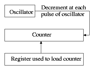
5.5.1 Clock Hardware
The hardware is simple.
It consists of
- An oscillator that generates a pulse at a know fixed
frequency.
- A counter that is decremented at each pulse.
- A register that can be used to reload the counter.
- Electronics that generate an interrupt whenever the counter
reaches zero.
The counter reload can be automatic or under OS control.
If it is done automatically, the interrupt occurs periodically
(the frequency is the oscillator frequency divided by the value in
the register).
The value in the register can be set by the operating system and
thus this programmable clock can be configured to
generate periodic interrupts and any desired frequency (providing
that frequency divides the oscillator frequency).
5.5.2 Clock Software
As we have just seen, the clock hardware simply generates a
periodic interrupt, called the clock interrupt, at
a set frequency.
Using this interrupt, the OS software can accomplish a number of
important tasks.
-
Time of day (TOD).
The basic idea is to increment a counter each clock tick (i.e.,
each interrupt).
The simplest solution is to initialize this counter at boot time
to the number of ticks since a fixed date (Unix traditionally
uses midnight, 1 January 1970).
Thus the counter always contains the number of ticks since that
date and hence the current date and time is easily calculated.
Two problems.
- From what value is the counter initialized?
- What about overflow?
Three methods are used for initialization.
The system can contact one or more know time sources (see the
Wikipedia entry for NTP),
the human operator can type in the date and time, or the
system can have a battery-powered, backup clock.
The last two methods only give an approximate time.
Overflow is a real problem if a 32-bit counter is used.
In this case two counters are kept, the low-order and the
high-order.
Only the low order is incremented each tick; the high order is
incremented whenever the low order overflows.
That is, a counter with more bits is simulated.
-
Time quantum for Round Robbin scheduling.
The system decrements a counter at each tick.
The quantum expires when the counter reaches zero.
The counter is loaded when the scheduler runs a process (i.e.,
changes the state of the process from ready to running).
This is what I (and I would guess you) did for the (processor)
scheduling lab.
-
Accounting.
At each tick, bump a counter in the process table
entry for the currently running process.
Alarm system call and system alarms.
Users can request a signal at some future time (the Unix
alarm
system call).
The system also on occasion needs to schedule some of its
own activities to occur at specific times in the future
(e.g., exercise a network time out).
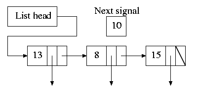
The conceptually simplest solution is to have one timer for
each event.
Instead, we simulate many timers with just one using the
data structure on the right with one node for each event.
- The first entry in each node is the time
after the preceding event that this event's
alarm is to ring.
- For example, if the time is zero, this event occurs at the
same time as the previous event.
- The second entry in the node is a pointer to the
action to perform.
- At each tick, the system decrements next-signal.
- When next-signal goes to zero, we process the first
entry on the list and any others immediately following
with a time of zero (which means they are to be
simultaneous with this alarm).
We then set next-signal to the value in the next alarm.
-
Profiling.
The objective is to obtain a histogram giving how much time
was spent in each software module of a given user program.
The program is logically divided into blocks of say 1KB and
a counter is associated with each block.
At each tick the profiled code checks the program counter
and bumps the appropriate counter.
After the program is run, a (user-mode) utility program
can determine the software module associated with each 1K
block and present the fraction of execution time spent in
each module.
If we use a finer granularity (say 10B instead of 1KB), we
get increased accuracy but more memory overhead.
Homework: 28.
5.5.3 Soft Timers
Skipped.
5.6 User Interfaces: Keyboard, Mouse, Monitor
5.6.2 Input Software
Keyboard Software
At each key press and key release a scan code
is written
into the keyboard controller and the computer is interrupted.
By remembering which keys have been depressed and not released the
software can determine Cntl-A, Shift-B, etc.
There are two fundamental modes of input, traditionally called
raw and cooked in Unix and now sometimes call
noncanonical
and canonical
in POSIX.
In raw mode the application sees every character
the user
types.
Indeed, raw mode is character oriented.
All the OS does is convert the keyboard scan codes
to characters
and and pass these characters to the
application.
For example
- down-cntl down-x up-x up-cntl is converted to cntl-x
- down-cntl up-cntl down-x up-x is converted to x
- down-cntl down-x up-cntl up-x is converted to cntl-x (I just
tried it to be sure).
- down-x down-cntl up-x up-cntl is converted to x
Full screen editors use this mode.
Cooked mode is line oriented.
The OS delivers lines to the application program after cooking them
as follows.
- Special characters are interpreted as editing characters
(erase-previous-character, erase-previous-word, kill-line, etc).
- Erased characters are not seen by the application but are
erased by the keyboard driver.
- Also needed is an escape character so that the editing
characters can be passed to the application if desired.
- The cooked characters must be echoed (what should one do if the
application is also generating output at this time?)
The (possibly cooked) characters must be buffered until the
application issues a read (and an end-of-line EOL has been
received for cooked mode).
Mouse Software
Whenever the mouse is moved or a button is pressed, it sends a
message to the computer consisting of Δx, Δy, and the
status of the buttons.
That is all the hardware does.
Issues such as double click
vs. two clicks are all handled by
the software.
5.6.3 Output Software
Text Windows
In the beginning these were essentially typewriters (called
glass ttys
) and therefore simply received a stream of
characters.
Soon after, they accepted commands (called escape sequences
)
that would position the cursor, insert and delete characters,
etc.
The X Window System
This is the window system on Unix machines.
From the very beginning it was a client-server system in which the
server (the display manager) could run on a separate machine from
the clients (graphical applications such as pdf viewers,
calendars, browsers, etc).
Graphical User Interfaces (GUIs)
This is a large subject that would take many lectures to cover well.
Both the hardware and the software are complex.
On a high-powered game computer, the graphics hardware is more
powerful and likely more expensive that the cpu on which the
operating system runs.
Bitmaps
Fonts
5.7 Thin Clients
5.8 Power Management
5.8.1 Hardware Issues
5.8.2 Operating System Issues
The Display
The Hard Disk
The CPU
The Memory
Wireless Communication
Thermal Management
Battery Management
Driver Interface
Application Program Issues
5.9 Research on Input/Output
5.10 Summary
Read.
The End: Good luck on the final