Consider the following characteristics of a disk.
- RPM (revolutions per minute).
- Seek time. This is actually quite complicated to calculate since you have to worry about, acceleration, travel time, deceleration, and "settling time".
- Rotational latency. The average value is the time for (approximately) one half a revolution.
- Transfer rate. This is determined by the RPM and bit density.
- Sectors per track. This is determined by the bit density.
- Tracks per surface (i.e., the number of cylinders). This is determined by the bit density.
- Tracks per cylinder (i.e, the number of surfaces).
Remark: A practice final is available off the web page. Note the format and good luck.
Overlapping I/O operations is important when the system has more than one disk. Many disk controllers can do overlapped seeks, i.e. issue a seek to one disk while another disk is already seeking.
As technology improves the space taken to store a bit decreases, i.e., the bit density increases. This changes the number of cylinders per inch of radius (the cylinders are closer together) and the number of bits per inch along a given track.
Despite what Tanenbaum says later, it is not true that when one head is reading from cylinder C, all the heads can read from cylinder C with no penalty. It is, however, true that the penalty is very small.
Choice of Block Size
Current commodity disks for desktop computers (not for commodity laptops) require about 10ms. before transferring the first byte and then transfer about 40K bytes per ms. (if contiguous). Specifically
- The rotation rate is normally 7200 RPM with 10k, 15k and 20k available.
- Recall that 6000 RPM is 100 rev/sec or one rev per 10ms. So half a revolution (the average rotation needed to reach a given point) is less than 5ms.
- Transfer rates are around 40MB/sec = 40KB/ms.
- Seek time is around 5ms.
This is quite extraordinary. For a large sequential transfer, in the first 10ms, no bytes are transmitted; in the next 10ms, 400,000 bytes are transmitted. The analysis suggests using large disk blocks, 100KB or more.
But the internal fragmentation would be severe since many files are small. Moreover, transferring small files would take longer with a 100KB block size.
In practice typical block sizes are 4KB-8KB.
Multiple block sizes have been tried (e.g. blocks are 8KB but a
file can also have fragments
that are a fraction of
a block, say 1KB).
Some systems employ techniques to encourage consecutive blocks of a given file to be stored near each other. In the best case, logically sequential blocks are also physically sequential and then the performance advantage of large block sizes is obtained without the disadvantages mentioned.
In a similar vein, some systems try to cluster related
files
(e.g., files in the same directory).
Homework: Consider a disk with an average seek time of 5ms, an average rotational latency of 5ms, and a transfer rate of 40MB/sec.
- If the block size is 1KB, how long would it take to read a block?
- If the block size is 100KB, how long would it take to read a block?
- If the goal is to read 1K, a 1KB block size is better as the remaining 99KB are wasted. If the goal is to read 100KB, the 100KB block size is better since the 1KB block size needs 100 seeks and 100 rotational latencies. What is the minimum size request for which a disk with a 100KB block size would complete faster than one with a 1KB block size?
Virtual Geometry and LBA (Logical Block Addressing)
Originally, a disk was implemented as a three dimensional array
Cylinder#, Head#, Sector#
The cylinder number determined the cylinder, the head number
specified the surface (recall that there is one head per surface),
i.e., the head number determined the track within the cylinder, and
the sector number determined the sector within the track.
But there is something wrong here. An outer track is longer (in centimeters) than an inner track, but each stores the same number of sectors. Essentially some space on the outer tracks was wasted.
Later disks lied. They said they had a virtual geometry as above, but really had more sectors on outer tracks (like a ragged array). The electronics on the disk converted between the published virtual geometry and the real geometry.
Modern disk continue to lie for backwards compatibility, but also support Logical Block Addressing in which the sectors are treated as a simple one dimensional array with no notion of cylinders and heads.
RAID (Redundant Array of Inexpensive Disks)
The name and its acronym RAID came from Dave Patterson's group at Berkeley. IBM changed the name to Redundant Array of Independent Disks. I wonder why?
The basic idea is to utilize multiple drives to simulate a single larger drive, but with added redundancy.
The different RAID configurations are often called different
levels, but this is not a good name since there is no hierarchy and
it is not clear that higher levels are better
than low ones.
However, the terminology is commonly used so I will follow the trend
and describe them level by level, but having very little to say
about some levels.
- Striping.
Consecutive blocks are interleaved across the multiple drives. The is no redundancy so it is strange to have it called RAID, but it is. Recall that a block may consist of multiple sectors.
- Mirroring.
The next level simply replicates the previous one. That is, the number of drives is doubled and two copies of each block are written, one in each of the two replicas. A read may access either replica. One might think that both replicas are read and compared, but this is not done, the drives themselves have check bits. The reason for having two replicas is to survive a single disk failure. In addition, read time is improved since the heads on one set of drives may be closer to the desired block.
- Synchronized disks, bit interleaved, multiple Hamming checksum
disks.
I don't believe this scheme is currently used.
- Synchronized disks, bit interleaved, single parity disk.
I don't believe this scheme is currently used.
- Striping plus a parity disk.
Use N (say 4) data disks and one parity disk. Data is striped across the data disks and the bitwise parity of these blocks is written in the corresponding block of the parity disk.- On a read, if the block is bad (e.g., if the entire disk is bad or even missing), the system automatically reads the other blocks in the stripe and the parity block in the stripe. Then the missing block is just the bitwise exclusive or (aka XOR) of all these blocks.
- For reads this is very good. The failure free case has no penalty (beyond the space overhead of the parity disk). The error case requires (N-1)+1=N (say 4) reads.
- A serious concern is the small write problem. Writing a sector requires 4 I/Os: Read the old data sector, compute the change, read the parity, compute the new parity, write the new parity and the new data sector. Hence one sector I/O became 4, which is a 300% penalty. Writing a full stripe is not bad. Compute the parity of the N (say 4) data sectors to be written and then write the data sectors and the parity sector. Thus 4 sector I/Os become 5, which is only a 25% penalty and is smaller for larger N, i.e., larger stripes.
- Rotated parity.
That is, for some stripes, disk 1 has the parity block; for others stripes, disk 2 has the parity; etc. The purpose is to avoid having a single parity disk since that disk is needed for all small writes and could easily become a point of contention.
CD-ROMs
CD-Recordables
CD-Rewritables
DVD
Blu-ray
5.4.2 Disk Formatting
5.4.3 Disk Arm Scheduling Algorithms
There are three components to disk response time: seek, rotational latency, and transfer time. Disk arm scheduling is concerned with minimizing seek time by reordering the requests.
These algorithms are relevant only if there are several I/O requests pending. For many PCs, the system is so underutilized that there are rarely multiple outstanding I/O requests and hence no scheduling is possible. At the other extreme, many large servers, are I/O bound with significant queues of pending I/O requests. For these systems, effective disk arm scheduling is crucial.
Although disk scheduling algorithms are performed by the OS, they are also sometimes implemented in the electronics on the disk itself. The disks I brought to class were somewhat old so I suspect those didn't implement scheduling, but the then-current operating systems definitely did.
We will study the following algorithms all of which are quite simple.
- FCFS (First Come First Served).
The most primitive. One could called thisno scheduling
, but I wouldn't. - Pick.
Same as FCFS but pick up requests for cylinders that are passed on the way to the next FCFS request. - SSTF or SSF (Shortest Seek (Time) First).
Use the greedy algorithm and go to the closest requested cylinder. This algorithm can starve requests. To prevent starvation, one can periodically enter a FCFS mode, but SSTF would still be unfair. Typically, cylinders in the middle receive better service than do cylinders on both extremes. - Scan (Look, Elevator).
This is the method used by an old fashioned jukebox (rememberHappy Days
) and by elevators.Those jukeboxesThe disk arm proceeds in one direction picking up all requests until there are no more requests in this direction at which point it goes back the other direction. This favors requests in the middle, but can't starve any requests.stole
coins since requesting an already requested song was a nop. - N-step Scan.
This is what the natural implementation of Scan actually does. The idea is that requests are serviced in batches. Specifically, it works as follows.- While the disk is servicing a Scan direction, the controller gathers up new requests and sorts them.
- At the end of the current sweep, the new list becomes the next sweep.
- Compare this to selfish round robin (SRR) with b≥a=0.
- C-Scan (C-look, Circular Scan/Look).
Similar to Scan but only service requests when moving in one direction. Let's assume it services requests when the head is moving from low-numbered cylinders to high-numbered one. When there are no pending requests for a cylinder with number higher than the present head location, the head is sent to the lowest-numbered, requested cylinder. C-Scan doesn't favor any spot on the disk. Indeed, it treats the cylinders as though they were a clock, i.e., after the highest numbered cylinder comes cylinder 0.
Minimizing Rotational Latency
Once the heads are on the correct cylinder, there may be several
requests to service.
All the systems I know, use Scan based on sector numbers to retrieve
these requests.
Note that in this case Scan is the same as C-Scan.
Why?
Ans: Because the disk rotates in only one direction.
The above is certainly correct for requests to the same track. If requests are for different tracks on the same cylinder, a question arises of how fast the disk can switch from reading one track to another on the same cylinder. There are two components to consider.
- How fast can it switch the electronics so that the signal from a different head is the one outputted by the disk?
- If the disk are is positioned so that one head is over cylinder k, are all the heads exactly over cylinder k.
parallel readoutdisk with with some network we had devised. Alas, a disk designer explained to me that the heads are not perfectly aligned with the tracks.
Homework: 24.
Homework: A salesman claimed that their version of Unix was very fast. For example, their disk driver used the elevator algorithm to reorder requests for different cylinders. In addition, the driver queued multiple requests for the same cylinder in sector order. Some hacker bought a version of the OS and tested it with a program that read 10,000 blocks randomly chosen across the disk. The new Unix was not faster that an old one that did FCFS for all requests. What happened?
Track Caching
Often the disk/controller caches (a significant portion of) the entire track whenever it access a block, since the seek and rotational latency penalties have already been paid. In fact modern disks have multi-megabyte caches that hold many recently read blocks. Since modern disks cheat and don't have the same number of blocks on each track, it is better for the disk electronics (and not the OS or controller) to do the caching since the disk is the only part of the system to know the true geometry.
5.4.4 Error Handling
Most disk errors are handled by the device/controller and not the
OS itself.
That is, disks are manufactured with more sectors than are
advertised and spares are used when a bad sector is referenced.
Older disks did not do this and the operating system would form
a secret file
of bad blocks that were never used.
5.4.A Ram Disks
- Fairly clear. Organize a region of memory as a set of blocks and pretend it is a disk.
- A problem is that memory is volatile.
- Often used during OS installation, before disk drivers are available (there are many types of disk but all memory looks the same so only one ram disk driver is needed).
5.4.5 Stable Storage
Skipped.
5.5 Clocks (Timers)
5.5.1 Clock Hardware
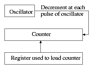
The hardware is simple. It consists of
- An oscillator that generates a pulse at a know fixed frequency.
- A counter that is decremented at each pulse.
- A register that can be used to reload the counter.
- Electronics that generate an interrupt whenever the counter reaches zero.
The counter reload can be automatic or under OS control. If it is done automatically, the interrupt occurs periodically (the frequency is the oscillator frequency divided by the value in the register).
The value in the register can be set by the operating system and thus this programmable clock can be configured to generate periodic interrupts and any desired frequency (providing that frequency divides the oscillator frequency).
5.5.2 Clock Software
As we have just seen, the clock hardware simply generates a periodic interrupt, called the clock interrupt, at a set frequency. Using this interrupt, the OS software can accomplish a number of important tasks.
-
Time of day (TOD).
The basic idea is to increment a counter each clock tick (i.e., each interrupt). The simplest solution is to initialize this counter at boot time to the number of ticks since a fixed date (Unix traditionally uses midnight, 1 January 1970). Thus the counter always contains the number of ticks since that date and hence the current date and time is easily calculated. Two problems.- From what value is the counter initialized?
- What about overflow?
Three methods are used for initialization. The system can contact one or more know time sources (see the Wikipedia entry for NTP), the human operator can type in the date and time, or the system can have a battery-powered, backup clock. The last two methods only give an approximate time.
Overflow is a real problem if a 32-bit counter is used. In this case two counters are kept, the low-order and the high-order. Only the low order is incremented each tick; the high order is incremented whenever the low order overflows. That is, a counter with more bits is simulated.
-
Time quantum for Round Robbin scheduling. The system decrements a counter at each tick. The quantum expires when the counter reaches zero. The counter is loaded when the scheduler runs a process (i.e., changes the state of the process from ready to running). This is what I (and I would guess you) did for the (processor) scheduling lab.
-
Accounting.
At each tick, bump a counter in the process table entry for the currently running process. 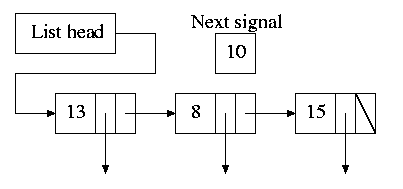
Alarm system call and system alarms.
Users can request a signal at some future time (the Unixalarm
system call). The system also on occasion needs to schedule some of its own activities to occur at specific times in the future (e.g., exercise a network time out).The conceptually simplest solution is to have one timer for each event. Instead, we simulate many timers with just one using the data structure on the right with one node for each event.
- The first entry in each node is the time after the preceding event that this event's alarm is to ring.
- For example, if the time is zero, this event occurs at the same time as the previous event.
- The second entry in the node is a pointer to the action to perform.
- At each tick, the system decrements next-signal.
- When next-signal goes to zero, we process the first entry on the list and any others immediately following with a time of zero (which means they are to be simultaneous with this alarm). We then set next-signal to the value in the next alarm.
-
Profiling.
The objective is to obtain a histogram giving how much time was spent in each software module of a given user program.The program is logically divided into blocks of say 1KB and a counter is associated with each block. At each tick the profiled code checks the program counter and bumps the appropriate counter.
After the program is run, a (user-mode) utility program can determine the software module associated with each 1K block and present the fraction of execution time spent in each module.
If we use a finer granularity (say 10B instead of 1KB), we get increased accuracy but more memory overhead.
Homework: 28.
5.5.3 Soft Timers
Skipped.
5.6 User Interfaces: Keyboard, Mouse, Monitor
5.6.2 Input Software
Keyboard Software
At each key press and key release a scan code
is written
into the keyboard controller and the computer is interrupted.
By remembering which keys have been depressed and not released the
software can determine Cntl-A, Shift-B, etc.
There are two fundamental modes of input, traditionally called
raw and cooked in Unix and now sometimes call
noncanonical
and canonical
in POSIX.
In raw mode the application sees every character
the user
types.
Indeed, raw mode is character oriented.
All the OS does is convert the keyboard scan codes
to characters
and and pass these characters to the
application.
For example
- down-cntl down-x up-x up-cntl is converted to cntl-x
- down-cntl up-cntl down-x up-x is converted to x
- down-cntl down-x up-cntl up-x is converted to cntl-x (I just tried it to be sure).
- down-x down-cntl up-x up-cntl is converted to x
Cooked mode is line oriented. The OS delivers lines to the application program after cooking them as follows.
- Special characters are interpreted as editing characters (erase-previous-character, erase-previous-word, kill-line, etc).
- Erased characters are not seen by the application but are erased by the keyboard driver.
- Also needed is an escape character so that the editing characters can be passed to the application if desired.
- The cooked characters must be echoed (what should one do if the application is also generating output at this time?)
The (possibly cooked) characters must be buffered until the application issues a read (and an end-of-line EOL has been received for cooked mode).
Mouse Software
Whenever the mouse is moved or a button is pressed, it sends a
message to the computer consisting of Δx, Δy, and the
status of the buttons.
That is all the hardware does.
Issues such as double click
vs. two clicks are all handled by
the software.
5.6.3 Output Software
Text Windows
In the beginning these were essentially typewriters (called
glass ttys
) and therefore simply received a stream of
characters.
Soon after, they accepted commands (called escape sequences
)
that would position the cursor, insert and delete characters,
etc.
The X Window System
This is the window system on Unix machines. From the very beginning it was a client-server system in which the server (the display manager) could run on a separate machine from the clients (graphical applications such as pdf viewers, calendars, browsers, etc).Graphical User Interfaces (GUIs)
This is a large subject that would take many lectures to cover well. Both the hardware and the software are complex. On a high-powered game computer, the graphics hardware is more powerful and likely more expensive that the cpu on which the operating system runs.Bitmaps
Fonts
5.7 Thin Clients
5.8 Power Management
5.8.1 Hardware Issues
5.8.2 Operating System Issues
The Display
The Hard Disk
The CPU
The Memory
Wireless Communication
Thermal Management
Battery Management
Driver Interface
Application Program Issues
5.9 Research on Input/Output
5.10 Summary
Read.
The End: Good luck on the final