Operating Systems
Start Lecture #13
4.3.5 Log-Structured File Systems
This research project of the early 1990s was inspired by the key
observation that systems are becoming limited in speed by
small writes.
The factors contributing to this phenomenon were (and still are).
- The CPU speed increases have far surpassed the disk speed
increases so the system has become I/O limited.
- The large buffer cache found on
modern systems has led to fewer read requests actually
requiring I/Os.
- A disk I/O requires almost 10ms of
preparation
before
any data is transferred, and then can transfer a block in less
than 1ms.
Thus, a one block transfer
spends most of its time
getting ready
to transfer.
The goal of the log-structured file system project was to design
a file system in which all writes are large and sequential (most
of the preparation is eliminated when writes are sequential).
These writes can be thought of as being appended to a log,
which gave the project its name.
- The project worked with a unix-like file system, i.e. it was
i-node based.
- The system accumulates writes in a buffer until have (say)
1MB to write.
- When the buffer is full, write it to the end of the disk (treating
the disk as a log).
- Thus writes are sequential and large and hence fast.
- When any part of a file is changed, the i-node is rewritten.
- The 1MB units on the disk are called (unfortunately) segments.
I will refer to the buffer as the segment buffer.
- A segment can contain i-nodes, direct blocks, indirect
blocks, blocks forming part of a file, and blocks forming part
of a directory.
In short a segment contains the most recently modified (or
created) 1MB of blocks.
- Note that the now useless overwritten blocks are not reclaimed!
- The system keeps a map of where the most recent version of
each i-node is located.
This map is on disk (but the heavily accessed parts will be in
the buffer cache).
- So the (most up to date) i-node of a file can be found and from
that the entire file can be found.
- But the disk will fill with garbage since modified blocks are not
reclaimed.
- A
cleaner
process runs in the background and examines
segments starting from the beginning.
It removes overwritten blocks and then adds the remaining
blocks to the segment buffer.
(This is very much not trivial.)
- Thus the disk is compacted and is treated like a circular array of
segments.
Despite the advantages given, log-structured file systems have
not caught on.
They are incompatible with existing file systems and the cleaner
has proved to be difficult.
4.3.6 Journaling File Systems
Many seemingly simple I/O operations are actually composed of
sub-actions.
For example, deleting a file on an i-node based system (really this
means deleting the last link to the i-node) requires
removing the entry from the directory, placing the i-node on the
free list, and placing the file blocks on the free list.
What happens if the system crashes during a delete and some, but
not all three, of the above actions occur?
- If the operations are guaranteed to be done in the order
given, then the worst that can occur is that the entry is
removed from the directory, but some file blocks and possibly
the i-node are not reclaimed.
This wastes resources, but is not a disaster.
- As we will learn later, I/O performance is sometimes improved
if operations are executed out of order.
- In that case we can have a directory entry pointing to an
i-node that has been freed or an i-node referring to blocks that
have been freed.
- Since free blocks and i-nodes are later reassigned to other
files, the results can be catastrophic.
A journaling file system prevents these problems by using an idea
from database theory, namely transaction logs.
To ensure that the multiple sub-actions are all performed, the
larger I/O operation (delete in the example) is broken into 3 steps.
- Write a log stating what has to be done and ensure it is
written to disk.
- Start doing the sub-actions.
- When all sub-actions complete, mark the log entry as complete
(and eventually erase it)..
After a crash, the log (called a journal) is examined and if there
are pending sub-actions, they are done before the system is made
available to users.
Since sub-actions may be repeated (once before the crash, and once
after), it is required that they all be idempotent
(applying the action twice is the same as applying it once).
Some history.
- IBM's AIX had a journaling file system in 1990.
- NTFS had journaling from day 1 (1993).
- Many Unix systems have it now.
- The main linux file system (ext2) added journaling (and became
ext3) in 2001.
Journaling appeared earlier that year in other Linux file
systems.
- Journaling was added to HFS+, the MacOS file system, in 2002.
- FAT has never had journaling.
4.3.7 Virtual File Systems
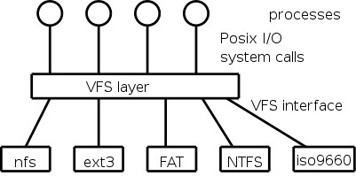
A single operating system needs to support a variety of file
systems.
The software support for each file system would have to handle the
various I/O system calls defined.
Not surprisingly the various file systems often have a great deal
in common and large parts of the implementations would be
essentially the same.
Thus for software engineering reasons one would like to abstract out
the common part.
This was done by Sun Microsystems when they introduced NFS the
Network File System for Unix and by now most unix-like operating
systems have adopted this idea.
The common code is called the VFS layer and is illustrated on the
right.
The original motivation for Sun was to support NFS (Network File
System), which permits a file system residing on machine A to be
mounted onto a file system residing on machine B.
The result is that by cd'ing to the appropriate directory on
machine B, a user with sufficient privileges can
read/write/execute the files in the machine A file system.
Note that mounting one file system onto another (whether they are
on different machines or not) does not require
that the two file systems be the same type.
For example, I routinely mount FAT file systems (from MP3 players,
cameras, ets) on to my Linux inode file system.
The involvement of multiple file system software components for a
single operation is another point in VFS's favor.
Nonetheless, I consider the idea of VFS to be mainly good
(perhaps superb) software engineering more than OS design.
The details are naturally OS specific.
4.4 File System Management and Optimization
Since I/O operations can dominate the time required for complete
user processes, considerable effort has been expended to improve the
performance of these operations.
4.4.1 Disk Space Management
All general purpose file systems use a (non-demand) paging
algorithm for file storage (read-only systems, which often use
contiguous allocation, are the major exception).
Files are broken into fixed size pieces,
called blocks that can be scattered over the disk.
Note that although this is paging, it is not called paging
(and may not have an explicit page table).
Actually, it is more complicated since various optimizations are
performed to try to have consecutive blocks of a single file stored
consecutively on the disk.
This is discussed below.
Note that all the blocks of the file are stored on the disk, i.e.,
it is not demand paging.
One can imagine systems that do utilize demand-paging-like
algorithms for disk block storage.
In such a system only some of the file blocks would be stored on
disk with the rest on tertiary storage (some kind of tape, or
holographic storage perhaps).
NASA might do this with their huge datasets.
Choice of Block Size
We discussed a similar question before when studying page size.
There are two conflicting goals, performance and efficiency.
- We will learn next chapter
that large disk transfers achieve much higher total
bandwidth than small transfers due to the comparatively
large
startup time
required before any bytes are
transferred.
This favors a large block size.
- Internal fragmentation favors a small block size.
This is especially true for small files, which would use only a
tiny fraction of a large block and thus waste much more than the
1/2 block average internal fragmentation found for random sizes.
For some systems, the vast majority of the space used is consumed
by the very largest files.
For example, it would be easy to have a few hundred gigabytes of
video.
In that case the space efficiency of small files is largely
irrelevant since most of the disk space is used by very large
files.
Typical block sizes today are 4KB and 8KB.
Keeping Track of Free Blocks
There are basically two possibilities, a bit map and a linked list.
Free Block Bitmap
A region of kernel memory is dedicated to keeping track of the free
blocks.
One bit is assigned to each block of the file system.
The bit is 1 if the block is free.
If the block size is 8KB the bitmap uses 1 bit for every 64
kilobits of disk space.
Thus a 64GB disk would require 1MB of RAM to hold its bitmap.
One can break the bitmap into (fixed size) pieces and apply demand
paging.
This saves RAM at the cost of increased I/O.
Linked List of Free Blocks
A naive implementation would simply link the free blocks together
and just keep a pointer to the head of the list.
This simple scheme has poor performance since it requires an extra
I/O for every acquisition or return of a free block.
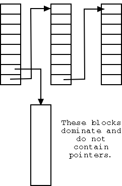
In the naive scheme a free disk block contains just one pointer;
whereas it could hold around a thousand of them.
The improved scheme, shown on the right, has only a small number of
the blocks on the list.
Those blocks point not only to the next block on the list, but also
to many other free blocks that are not directly on the list.
As a result only one in about 1000 requests for a free block
requires an extra I/O, a great improvement.
Unfortunately, a bad case still remains.
Assume the head block on the list is exhausted, i.e. points only to
the next block on the list.
A request for a free block will receive this block, and the next one
on the list is brought it.
It is full of pointers to free blocks not on the list (so far so
good).
If a free block is now returned we repeat the process and get back
to the in-memory block being exhausted.
This can repeat forever, with one extra I/O per request.
Tanenbaum shows an improvement where you try to keep the one
in-memory free block half full of pointers.
Similar considerations apply when splitting and coalescing nodes in
a B-tree.
Disk Quotas
Two limits can be placed on disk blocks owned by a given user, the
so called soft
and hard
limits.
A user is never permitted to exceed the hard limit.
This limitation is enforced by having system calls such
as write return failure if the user is already at the hard
limit.
A user is permitted to exceed the soft limit during a login session
provided it is corrected prior to logout.
This limitation is enforced by forbidding logins (or issuing a
warning) if the user is above the soft limit.
Often files on directories such as /tmp are not counted towards
either limit since the system is permitted to deleted these files
when needed.
4.4.2 File System Backups (a.k.a. Dumps)
A physical backup simply copies every block in
order onto a tape (or other backup media).
It is simple and useful for disaster protection, but not useful for
retrieving individual files.
We will study logical backups, i.e., dumps that
are file and directory based not simply block based.
Tanenbaum describes the (four phase) unix dump algorithm.
All modern systems support full and
incremental dumps.
- A level 0 dump is a called a full dump (i.e., dumps everything).
- A level n dump (n>0) is called an incremental dump and the
standard unix utility backs up all files that have changed since
the most recent dump of level k<n.
- Some other dump utilities dump all files that have changed
since the most recent dump at level k≤n.
- Assume a level 4 dump is done on sunday and a level 5 is done
on the other 6 days of the week (I personally use this scheme).
On thursday, the unix dump will have all files that changed
since sunday and thus will be bigger than wednesday's dump.
The other style dump will only dump the files that changed since
wednesday and hence daily dumps will be about the same size.
- Restoring a unix dump would require restoring the most recent
level-0, level-4, and level-5.
The other dump style would require level-0, level-4, and all
level-5s since the last level-4.
- The system keeps on the disk the dates of the most recent
level i dumps for all i so that the dump program can determine
which files need to be dumped for a level-k incremental.
In Unix these dates are traditionally kept in the file
/etc/dumpdates.
- What about the nodump attribute?
- Default policy (for Linux at least) is to dump such files
anyway when doing a full dump, but not dump them for incremental
dumps.
- Another way to say this is the nodump attribute is honored for
level n dumps if n>0.
- The dump command has an option to override the default policy
(can specify k so that nodump is honored for level n dumps if n>k).
An interesting problem is that tape densities are increasing slower
than disk densities so an ever larger number of tapes are needed to
dump a full disk.
This has lead to disk-to-disk dumps; another possibility is to utilize
raid, which we study next chapter.
4.4.3 File System Consistency
Modern systems have utility programs that check the consistency of
a file system.
A different utility is needed for each file system type in the
system, but a wrapper
program is often created so that the
user is unaware of the different utilities.
The unix utility is called fsck (file system check) and the window
utility is called chkdsk (check disk).
- If the system crashed, it is possible that not all metadata was
written to disk.
As a result the file system may be inconsistent.
These programs check, and often correct, inconsistencies.
- Scan all i-nodes (or fat) to check that each block is in exactly
one file, or on the free list, but not both.
- Also check that the number of links to each file (part of the
metadata in the file's i-node) is correct (by
looking at all directories).
- Other checks as well.
- Offers to
fix
the errors found (for most errors).
Bad blocks on disks
Not so much of a problem now.
Disks are more reliable and, more importantly, disks and disk
controllers take care most bad blocks themselves.
4.4.4 File System Performance
Caching
Demand paging again!
Demand paging is a form of caching:
Conceptually, the process resides on disk (the big and slow medium)
and only a portion of the process (hopefully a small portion that is
heavily access) resides in memory (the small and fast medium).
The same idea can be applied to files.
The file resides on disk but a portion is kept in memory.
The area in memory used to for those file blocks is called the
buffer cache or block cache.
Some form of LRU replacement is used.
The buffer cache is clearly good and simple for blocks that are
only read.
What about writes?
Homework: 27.
Block Read Ahead
When the access pattern looks
sequential, read ahead is
employed.
This means that after completing a read() request for block n of a
file, the system guesses that a read() request for block n+1 will
shortly be issued and hence automatically fetches block n+1.
- How does the system decide that the access pattern looks sequential?
- If a seek system call is issued, the access pattern is not
sequential.
- If a process issues consecutive read() system calls for
block n-1 and then n, the access patters is guessed to be
sequential.
- What if block n+1 is already in the block cache?
Ans: Don't issue the read ahead.
- Would it be reasonable to read ahead two or three blocks?
Ans: Yes.
- Would it be reasonable to read ahead the entire file?
Ans: No, it could easily pollute the cache evicting needed blocks, and
could waste considerable disk bandwidth.
Reducing Disk Arm Motion
The idea is to try to place near each other blocks that are likely
to be accessed sequentially.
- If the system uses a bitmap for the free list, it can
allocate a new block for a file close to the previous block
(guessing that the file will be accessed sequentially).
- The system can perform allocations in
super-blocks
, consisting
of several contiguous blocks.
- The block cache and I/O requests are still in blocks not
super-blocks.
- If the file is accessed sequentially, consecutive blocks of a
super-block will be accessed in sequence and these are
contiguous on the disk.
- For a unix-like file system, the i-nodes can be placed in the
middle of the disk, instead of at one end, to reduce the
seek time needed to access an i-node
followed by a block of the file.
- The system can logically divide the disk into
cylinder groups, each of which is a
consecutive group of cylinders.
- Each cylinder group has its own free list and, for a unix-like
file system, its own space for i-nodes.
- If possible, the blocks for a file are allocated in the same
cylinder group as the i-node.
- This reduces seek time if consecutive accesses are for the
same file.
4.4.5 Defragmenting Disks
If clustering is not done, files can become spread out all over
the disk and a utility (defrag on windows) should be run to make
the files contiguous on the disk.
4.5 Example File Systems
4.5.A The CP/M File System
CP/M was a very early and simple OS.
It ran on primitive hardware with very little ram and disk space.
CP/M had only one directory in the entire system.
The directory entry for a file contained pointers to the disk blocks
of the file.
If the file contained more blocks than could fit in a directory
entry, a second entry was used.
4.5.1 CD-ROM File Systems
File systems on cdroms do not need to support file addition or
deletion and as a result have no need for free blocks.
A CD-R (recordable) does permit files to be added, but they are
always added at the end of the disk.
The space allocated to a file is not recovered even when the file is
deleted, so the (implicit) free list is simply the blocks after the
last file recorded.
The result is that the file systems for these devices are quite
simple.
The ISO9660 File System
This international standard forms the basis for essentially all
file systems on data cdroms (music cdroms are different and are not
discussed).
Most Unix systems use iso9660 with the Rock Ridge extensions, and
most windows systems use iso9660 with the Joliet extensions.
The ISO9660 standard permits a single physical CD to be partitioned
and permits a cdrom file system to span many physical CDs.
However, these features are rarely used and we will not discuss
them.
Since files do not change, they are stored contiguously and each
directory entry need only give the starting location and file length.
File names are 8+3 characters (directory names just 8) for
iso9660-level-1 and 31 characters for -level-2.
There is also a -level-3 in which a file is composed of extents
which can be shared among files and even shared within a single file
(i.e. a single physical extent can occur multiple times in a given
file).
Directories can be nested only 8 deep.
Rock Ridge Extensions
The Rock Ridge extensions were designed by a committee from the
unix community to permit a unix file system to be copied to a cdrom
without information loss.
These extensions included.
- The unix rwx bits for permissions.
- Major and Minor numbers to support
special files
,
i.e. including devices in the file system name structure.
- Symbolic links.
- An alternate (long) name for files and directories.
- A somewhat kludgy work around for the limited directory
nesting levels.
- Unix timestamps (creation, last access, last modification).
Joliet Extensions
The Joliet extensions were designed by Microsoft to permit a
windows file system to be copied to a cdrom without information
loss.
These extensions included.
- Long file names.
- Unicode.
- Arbitrary depth of directory nesting.
- Directory names with extensions.
4.5.2 The MS-DOS (and Windows FAT) File System
We discussed this linked-list, File-Allocation-Table-based file
system previously.
Here we add a little history.
MS-DOS and Early Windows
The FAT file system has been supported since the first IBM PC
(1981) and is still widely used.
Indeed, considering the number of cameras and MP3 players, it is
very widely used.
Unlike CP/M, MS-DOS always had support for subdirectories and
metadata such as date and size.
File names were restricted in length to 8+3.
As described above, the directory entries point to the first
block of each file and the FAT contains pointers to the remaining
blocks.
The free list was supported by using a special code in the FAT for
free blocks.
You can think of this as a bitmap with a wide bit
.
The first version FAT-12 used 12-bit block numbers so a partition
could not exceed 212 blocks.
A subsequent release went to FAT-16.
The Windows 98 File System
Two changes were made: Long file names were supported and the
file allocation table was switched from FAT-16 to FAT-32.
These changes first appeared in the second release of Windows 95.
Long File Names
The hard part of supporting long names was keeping compatibility
with the old 8+3 naming rule.
That is, new file systems created with windows 98 using long file
names must be accessible if the file system is subsequently used
with an older version of windows that supported only 8+3 file names.
The ability for new old systems to read data from new systems was
important since users often had both new and old systems and kept
many files on floppy disks that were used on both systems.
This abiliity called backwards compatibility
.
The solution was to permit a file to have two names: a long one and
an 8+3 one.
The primary directory entry for a file in windows 98 is the same
format as it was in MS-DOS and contains the 8+3 file name.
If the long name fits the 8+3 format, the story ends here.
If the long name does not fit in 8+3, an 8+3 version is produce
via an algorithm that works but produces names with severely
limited aesthetic value.
The long name is stored in one or more axillary
directory
entries adjacent to the main entry.
These axillary entries are set up to appear invalid to the old OS,
which therefore ignores them.
FAT-32
FAT-32 used 32 bit words for the block numbers (actually, it used
28 bits) so the FAT could be huge (228 entries).
Windows 98 kept only a portion of the FAT-32 table in memory at a
time.
4.5.3 The Unix V7 File System
I presented the inode system in some detail
above.
Here we just describe a few properties of the filesystem beyond the
inode structure itself.
- Each directory entry contains a name and a pointer to the
corresponding i-node.
- The metadata for a file or directory is stored in the
corresponding inode.
- Early unix limited file names to 14 characters, stored in a
fixed length field.
- The name field now is of varying length and file names can be
quite long.
On my linux system
touch 255-char-name
is OK but
touch 256-char-name
is not.
- To go down a level in the directory hierarchy takes two steps:
get the inode, get the file (or subdirectory).
- This shows how important it is not to parse filenames for each I/O
operation, i.e., why the open() system call is important.
- Do on the blackboard the steps for
/a/b/X
4.6 Research on File Systems
Skipped
4.6 Summary
Read
Chapter 5 Input/Output
5.1 Principles of I/O Hardware
5.1.1 I/O Devices
The most noticeable characteristic of current ensemble of I/O
devices is their great diversity.
- Some, e.g. disks, transmit megabytes per second; others, like
keyboards, don't transmit a megabyte in their lifetime.
- Some, like ethernet, are purely electronic; others, like disks
are mechanical marvels.
- A mouse can be put in your pocket; a high-speed printer needs
at least two people to move it.
- Some devices, e.g. a keyboard, are input only.
But note that this is in some sense a crazy classification since
a keyboard produces output, which is sent to the computer, and
receives very little input from the computer (mostly to turn
on/off a few lights).
Really a keyboard is a transducer, taking mechanical input from
a human and producing electronic output for a computer.
- Similarly, an
output only
device such as a printer
supplies very little output to the computer (perhaps an out of
paper indication) but receives voluminous input from the
computer.
Again it is better thought of as a transducer, converting
electronic data from the computer to paper data for humans.
- Many devices are input/output, but again the words can be
funny.
A disk is viewed as an input device when it is being read, i.e.,
when it is outputting data; it is viewed as an output device
when it is inputting data.
- Often devices are characterized as
block devices or as
character devices.
The distinction being that devices like disks are read/written
in blocks and individual blocks can be addressed (i.e., not all
accesses are sequential).
An ethernet interface or a printer has no notion of block or
addresses.
Instead, it just deals with a stream of characters.
- However, the block/character device
distinction is fuzzy.
What about tapes?
They read/write blocks and are sort of block addressable (rewind
then skip forward).
Clocks are weird and hard to classify; they simply generate
periodic interrupts.
5.1.2 Device Controllers
These are the devices as far as the OS is concerned.
That is, the OS code is written with the controller specification in
hand not with the device specification.
- Controllers are also called adaptors.
- A controller abstracts away some of the low level features of
the devices it controls.
For example, a disk controller performs error checking and
assembles the bit stream coming off the disk into blocks of
bytes.
- In the old days controllers handled
interleaving of sectors.
Sectors are interleaved if the controller or CPU cannot handle
the data rate and would otherwise have to wait a full revolution
between sectors.
This is not a concern with modern systems since the electronics
have increased in speed faster than the devices and now all disk
controllers can handle the full data rate of the disks they
support.
- Graphics controller do a great deal.
They often contain processors at least as powerful as the main CPU
on which the OS runs.
5.1.3 Memory-Mapped I/O (vs I/O Space Instructions)
Consider a disk controller processing a read request.
The goal is to copy data from the disk to some portion of the
central memory.
How is this to be accomplished?
The controller contains a microprocessor and memory, and is
connected to the disk (by wires).
When the controller requests a sector from the disk, the sector is
transmitted to the control via the wires and is stored by the
controller in its memory.
The separate processor and memory on the controller gives rise to
two questions.
- How does the OS request that the controller, which is running
on another processor, perform an I/O and how are the parameters
of the request transmitted to the controller?
- How are the data from a disk read moved from the controller's
memory to the general system memory?
Similarly, how is the write data moved to the controller?
Typically the interface the OS sees consists of some several
registers located on the controller.
- These are memory locations into which the OS writes
information such as the sector to access, read vs. write,
length, where in system memory to put the data (for a read) or
from where to take the data (for a write).
- There is also typically a device register that acts as a
go button
.
- There are also devices registers that the OS reads, such as
the status of the controller, any errors that were detected,
etc.
So the first question above becomes, how does the OS read and write
the device register?
- With memory-mapped I/O the device registers
appear as normal memory.
All that is needed is to know at which address each device
register appears.
Then the OS uses normal load and store instructions to read
and write the registers.
- Some systems instead have a special
I/O space
into
which the registers are mapped.
In this case special I/O space instructions are used to
accomplish the loads and stores.
- From a conceptual point of view there is no
difference between the two models, but the implementations
differ.
For example.
- Memory-mapped I/O is a more
elegant
solution in
that it uses an existing mechanism to accomplish a second
objective.
- Since normal loads and stores are used for memory-mapped
I/O, the algorithm can be written in a high-level
language.
Assembly language is needed for I/O space instructions
since such instructions cannot be expressed in (normal)
high-level languages.
- A memory-mapped implementation must arrange that these
addresses are sent to the appropriate bus and must insure
that they are not cached.
5.1.4: Direct Memory Access (DMA)
We now address the second question, moving data between the
controller and the main memory.
Recall that (independent of the issue with respect to DMA) the disk
controller, when processing a read request pulls the desired data
from the disk to its own buffer (and pushes data from the buffer to
the disk when processing a write).
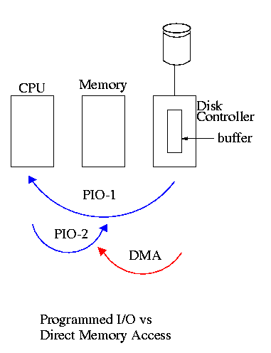
Without DMA, i.e., with programmed I/O (PIO), the
cpu then does loads and stores (assuming the controller buffer is
memory mapped, or uses I/O instructions if it is not) to copy the data
from the buffer to the desired memory locations.
A DMA controller, instead writes the main memory itself, without
intervention of the CPU.
Clearly DMA saves CPU work.
But this might not be important if the CPU is limited by the memory
or by system buses.
An important point is that there is less data movement with DMA so
the buses are used less and the entire operation takes less
time.
Compare the two blue arrows vs. the single red arrow.
Since PIO is pure software it is easier to change, which is an
advantage.
DMA does need a number of bus transfers from the CPU to the
controller to specify the DMA.
So DMA is most effective for large transfers where the setup is
amortized.
A serious conceptual difference with DMA is that the bus now has
multiple masters
and hence requires arbitration,
which leads to issues we faced with critical sections.
Why have the buffer?
Why not just go from the disk straight to the memory?
- Speed matching.
The disk supplies data at a fixed rate, which might exceed the
rate the memory can accept it.
In particular the memory might be busy servicing a request from
the processor or from another DMA controller.
Alternatively, the disk might supply data at a slower rate than
the memory (and memory bus) can handle thus under-utilizing an
important system resource.
- Error detection and correction.
The disk controller verifies the checksum written on the disk.
Homework: 12
5.1.5 Interrupts Revisited
Precise and Imprecise Interrupts
5.2 Principles of I/O Software
As with any large software system, good design and layering is
important.
5.2.1 Goals of the I/O Software
Device Independence
We want to have most of the OS to be unaware of the characteristics
of the specific devices attached to the system.
(This principle of device independence is not limited to I/O; we
also want the OS to be largely unaware of the CPU type itself.)
This objective has been accomplished quite well for files stored on
various devices.
Most of the OS, including the file system code, and most
applications can read or write a file without knowing if the file is
stored on a floppy disk, an internal SATA hard disk, an external
USB SCSI disk, an external USB Flash Ram, a tape, or (for reading) a
CD-ROM.
This principle also applies for user programs reading or writing
streams.
A program reading from ``standard input'', which is normally the
user's keyboard can be told to instead read from a disk file with no
change to the application program.
Similarly, ``standard output'' can be redirected to a disk file.
However, the low-level OS code dealing with disks is rather different
from that dealing keyboards and (character-oriented) terminals.
One can say that device independence permits programs to be
implemented as if they will read and write generic or abstract
devices, with the actual devices specified at run time.
Although writing to a disk has differences from writing to a
terminal, Unix cp, DOS copy, and
many programs we compose need not be aware of these differences.
However, there are devices that really are special.
The graphics interface to a monitor (that is, the graphics interface
presented by the video controller—often called a ``video
card'') does not resemble the ``stream of bytes'' we see for disk
files.
Homework:
What is device independence?
Uniform naming
We have already discussed the value of
the name space implemented by file systems.
There is no dependence between the name of the file and the device
on which it is stored.
So a file called IAmStoredOnAHardDisk might well be stored on a
floppy disk.
More interesting once a device is mounted on (Unix) directory, the
device is named exactly the same as the directory was.
So if a CD-ROM was mounted on (existing) directory /x/y, a file
named joe on the CD-ROM would now be accessible as /x/y/joe.
Error handling
There are several aspects to error handling including: detection,
correction (if possible) and reporting.
-
Detection should be done as close to where the error occurred
as possible before more damage is done (fault containment).
Moreover, the error may be obvious at the low level, but
harder to discover and classify if the erroneous data is
passed to higher level software.
-
Correction is sometimes easy, for example ECC memory does
this automatically (but the OS wants to know about the error
so that it can request replacement of the faulty chips before
unrecoverable double errors occur).
Other easy cases include successful retries for failed
ethernet transmissions.
In this example, while logging is appropriate, it is quite
reasonable for no action to be taken.
-
Error reporting tends to be awful.
The trouble is that the error occurs at a low level but by the
time it is reported the context is lost.
Creating the illusion of synchronous I/O
I/O must be asynchronous for good performance.
That is the OS cannot simply wait for an I/O to complete.
Instead, it proceeds with other activities and responds to the
interrupt that is generated when the I/O has finished.
Users (mostly) want no part of this.
The code sequence
    Read X
    Y = X+1
    Print Y
should print a value one greater than that read.
But if the assignment is performed before the read completes, the
wrong value can easily be printed.
Performance junkies sometimes do want the asynchrony so
that they can have another portion of their program executed while
the I/O is underway.
That is, they implement a mini-scheduler in their application
code.
See this message from linux kernel
developer Ingo Molnar for his take on asynchronous IO and
kernel/user threads/processes.
You can find the entire discussion
here.
Buffering
Buffering is often needed to hold data for examination prior to
sending it to its desired destination.
Since this involves copying the data, which can be expensive,
modern systems try to avoid as much buffering as possible.
This is especially noticeable in network transmissions, where the
data could conceivably be copied many times.
- From user space to kernel space as part of the write system
call.
- From kernel space to a kernel I/O buffer.
- From the I/O buffer to a buffer on the network adaptor.
- From the adapter on the source to the adapter on the destination.
- From the destination adapter to an I/O buffer.
- From the I/O buffer to kernel space.
- From kernel space to user space as part of the read system
call.
I am not sure if any systems actually do all seven.
Sharable vs. Dedicated Devices
For devices like printers and CD-ROM drives, only one user at a
time is permitted.
These are called serially reusable devices, which
we studied in the deadlocks chapter.
Devices such as disks and ethernet ports can, on the contrary, be
shared by concurrent processes without any deadlock risk.
5.2.2 Programmed I/O
As mentioned just above, with programmed I/O the
main processor (i.e., the one on which the OS runs) moves the data
between memory and the device.
This is the most straightforward method for performing I/O.
One question that arises is how does the processor know when the
device is ready to accept or supply new data.
In the simplest implementation, the processor, when it seeks to use
a device, loops continually querying the device status, until the
device reports that it is free.
This is called polling or
busy waiting.
    loop
        if device-available then exit loop
        do-useful-work
If we poll infrequently (and do useful work in between), there can
be a significant delay from when the previous I/O is complete to when
the OS detects the device availability.
If we poll frequently (and thus are able to do little useful work
in between) and the device is (sometimes) slow, polling is clearly
wasteful.
The extreme case is where the process does nothing between polls.
For a slow device this can take the CPU out of service for a
significant period.
This bad situation leads us to ... .
5.2.3 Interrupt-Driven (Programmed) I/O
As we have just seen, a difficulty with polling is determining the
frequency with which to poll.
Another problem is that the OS must continually return to the
polling loop, i.e., we must arrange that do-useful-work takes the
desired amount of time.
Really we want the device to tell the CPU when it is available,
which is exactly what an interrupt does.
The device interrupts the processor when it is ready and an
interrupt handler (a.k.a. an interrupt service routine) then
initiates transfer of the next datum.
Normally interrupt schemes perform better than polling, but not
always since
interrupts are expensive on modern machines.
To minimize interrupts, better controllers often employ ...
5.2.4 I/O Using DMA
We discussed DMA above.
An additional advantage of dma, not mentioned above, is that the
processor is interrupted only at the end of a command not after each
datum is transferred.
Many devices receive a character at a time, but with a dma
controller, an interrupt occurs only after a buffer has been
transferred.
5.3 I/O Software Layers
Layers of abstraction as usual prove to be effective.
Most systems are believed to use the following layers (but for many
systems, the OS code is not available for inspection).
- User-level I/O routines.
- Device-independent (kernel-level) I/O software.
- Device drivers.
- Interrupt handlers.
We will give a bottom up explanation.
5.3.1 Interrupt Handlers
We discussed the behavior of an interrupt handler
before when studying page faults.
Then it was called assembly-language code
.
A difference is that page faults are caused by specific user
instructions, whereas interrupts just occur
.
However, the assembly-language code
for a page fault
accomplishes essentially the same task as the interrupt handler does
for I/O.
In the present case, we have a process blocked on I/O and the I/O
event has just completed.
So the goal is to make the process ready and then call the
scheduler.
Possible methods are.
- Releasing a semaphore on which the process is waiting.
- Sending a message to the process.
- Inserting the process table entry onto the ready list.
Once the process is ready, it is up to the scheduler to decide when
it should run.
5.3.2 Device Drivers
Device drivers form the portion of the OS that is tailored to the
characteristics of individual controllers.
They form the dominant portion of the source code of the OS since
there are hundreds of drivers.
Normally some mechanism is used so that the only drivers loaded on a
given system are those corresponding to hardware actually present.
Indeed, modern systems often have loadable device drivers
,
which are loaded dynamically when needed.
This way if a user buys a new device, no changes to the operating
system are needed.
When the device is installed it will be detected during the boot
process and the corresponding driver is loaded.
Sometimes an even fancier method is used and the device can be
plugged in while the system is running (USB devices are like this).
In this case it is the device insertion that is detected by the OS
and that causes the driver to be loaded.
Some systems can dynamically unload a driver, when
the corresponding device is unplugged.
The driver has two parts
corresponding to its two access
points.
Recall the figure at the upper right, which we saw at the beginning
of the course.
- The driver is accessed by the main line OS via the envelope in
response to an I/O system call.
The portion of the driver accessed in this way is sometimes called
the
top
part.
- The driver is also accessed by the interrupt handler when the
I/O completes (this completion is signaled by an interrupt).
The portion of the driver accessed in this way is sometimes call
the
bottom
part.
In some system the drivers are implemented as user-mode processes.
Indeed, Tannenbaum's MINIX system works that way, and in previous
editions of the text, he describes such a scheme.
However, most systems have the drivers in the kernel itself and the
3e describes this scheme.
I previously included both descriptions, but have eliminated the
user-mode process description (actually I greyed it out).
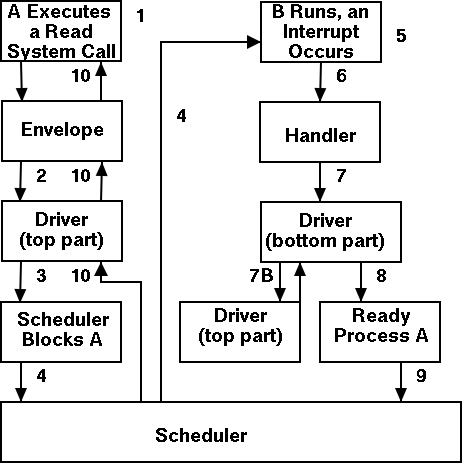
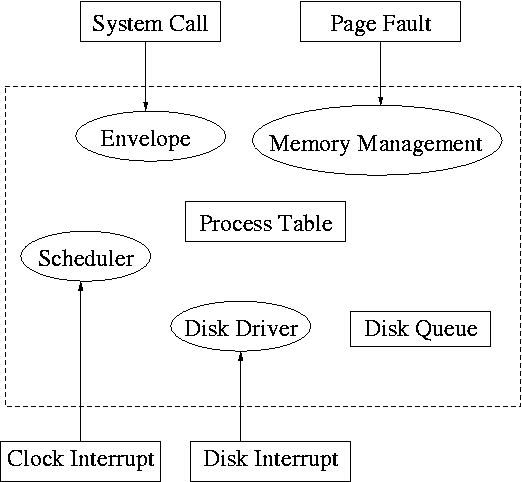
Driver in a self-service paradigm
The numbers in the diagram to the right correspond to the numbered
steps in the description that follows.
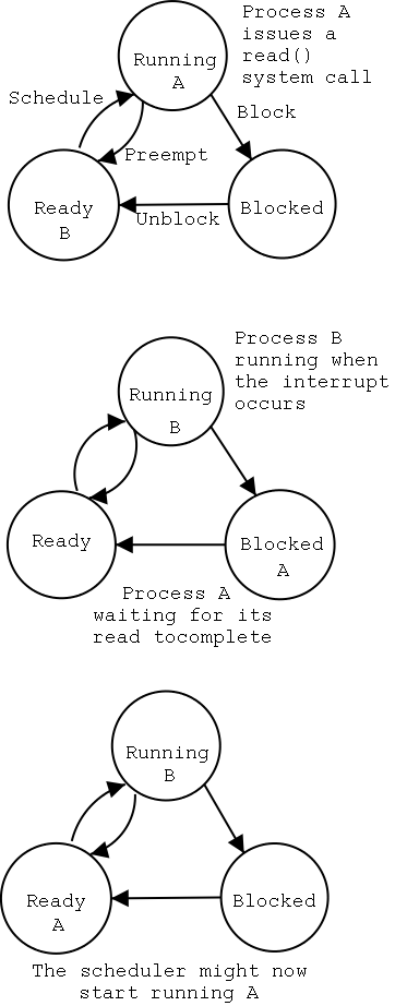
The bottom diagram shows the state of processes A and B at steps 1,
6, and 9 in the execution sequence described.
What follows is the Unix-like view in which the driver is invoked
by the OS acting in behalf of a user process (alternatively stated,
the process shifts into kernel mode).
Thus one says that the scheme follows a self-service
paradigm
in that the process itself (now in kernel mode) executes the driver.
- The user (A) issues an I/O system call.
- The main line, machine independent, OS prepares a
generic request for the driver and calls (the top part of)
the driver.
- If the driver was idle (i.e., the controller was idle), the
driver writes device registers on the controller ending with a
command for the controller to begin the actual I/O.
- If the controller was busy (doing work the driver gave it
previously), the driver simply queues the current request (the
driver dequeues this request below).
- The driver jumps to the scheduler indicating that the current
process should be blocked.
- The scheduler blocks A and runs (say) B.
- B starts running.
- An interrupt arrives (i.e., an I/O has been completed) and the
handler is invoked.
- The interrupt handler invokes (the bottom part of) the driver.
- The driver informs the main line perhaps passing data and
surely passing status (error, OK).
- The top part is called to start another I/O if the queue is
nonempty. We know the controller is free. Why?
Answer: We just received an interrupt saying so.
- The driver jumps to the scheduler indicating that process A should
be made ready.
- The scheduler picks a ready process to run. Assume it picks A.
- A resumes in the driver, which returns to the main line, which
returns to the user code.
Driver as a Process (Less Detailed Than Above)
Actions that occur when the user issues an I/O request.
- The main line OS prepares a generic request (e.g. read, not
read using Buslogic BT-958 SCSI controller) for the driver and
the driver is awakened.
Perhaps a message is sent to the driver to do both jobs.
- The driver wakes up.
- If the driver was idle (i.e., the controller is idle), the
driver writes device registers on the controller ending with a
command for the controller to begin the actual I/O.
- If the controller is busy (doing work the driver gave it), the
driver simply queues the current request (the driver dequeues this
below).
- The driver blocks waiting for an interrupt or for more
requests.
Actions that occur when an interrupt arrives (i.e., when an I/O has
been completed).
- The driver wakes up.
- The driver informs the main line perhaps passing data and
surely passing status (error, OK).
- The driver finds the next work item or blocks.
- If the queue of requests is non-empty, dequeue one and
proceed as if just received a request from the main line.
- If queue is empty, the driver blocks waiting for an
interrupt or a request from the main line.