Start Lecture #12
Homework: Start Reading Chapter 5.
We are going to build
a basic MIPS processor.
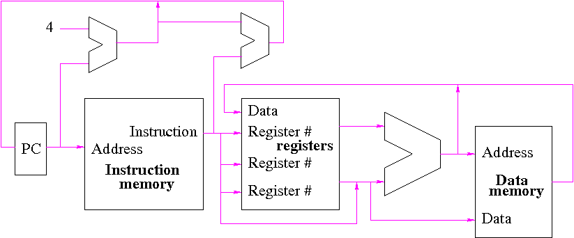
Figure 5.1 redrawn below shows the main idea
Note that the instruction gives the three register numbers as well as an immediate value to be added.
Done in appendix B.
Let's begin doing the pieces in more detail.
We draw buses in magenta (mostly 32 bits) and control lines in green.
We are ignoring branches and jumps for now.
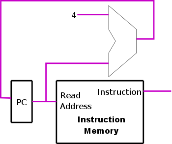
The diagram on the right shows the main loop
involving
instruction fetch (i-fetch)
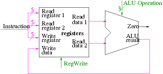
We did the register file in appendix B. Recall the following points made when discussing the appendix.
Readand
Writein the diagram are adjectives not verbs.
write registeris to be written. We know that is always the case for R-type instructions.
The 32-bit bus with the instruction is divided into three 5-bit buses for each register number (plus other wires not shown).
Homework: What would happen if the RegWrite line had a stuck-at-0 fault (was always deasserted)? What would happen if the RegWrite line had a stuck-at-1 fault (was always asserted)?
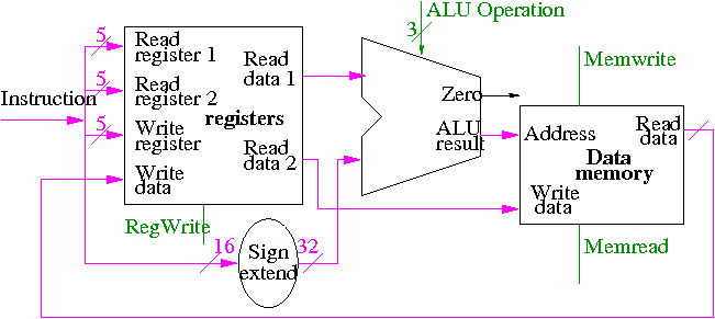
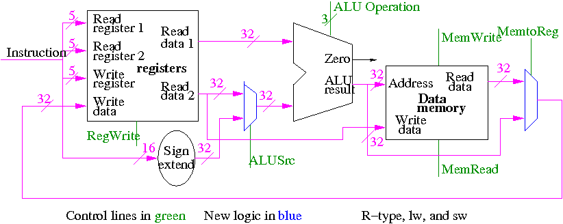
The diagram on the right shows the structures used to implement load word and store word (lw and sw).
lw $r,disp($s):
disp(displacement) to the contents of register $s.
sw $r,disp($s):
We have a 32-bit adder and more importantly have a 32-bit addend coming from the register file. Hence we need to extend the 16-bit immediate constant to 32 bits. That is we must replicate the HOB of the 16-bit immediate constant to produce an additional 16 HOBs all equal to the sign bit of the 16-bit immediate constant. This is called sign extending the constant.
What about the control lines?
addfor lw and sw.
Homework: What would happen if the RegWrite line
had a stuck-at-0 fault (was always deasserted)?
What would happen if the RegWrite line
had a stuck-at-1 fault (was always asserted)?
What would happen if the MemWrite line
had a stuck-at-0 fault (was always deasserted)?
What would happen if the MemWrite line
had a stuck-at-1 fault (was always asserted)?
The diagram cheats a little for clarity.
mux deficient.
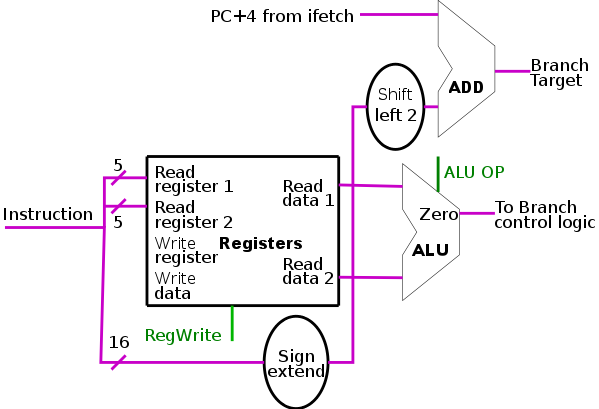
Compare two registers and branch if equal. Recall the following from appendix B, where we built the ALU, and from chapter 2, where we discussed beq.
disp(treated as a signed number) left shifted 2 bits (because the constant represent words and the address is specified in bytes.
The top alu labeled add
is just an adder so does not need
any control
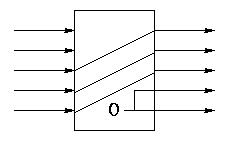
The shift left 2 is not a shifter. It simply moves wires and includes two zero wires. We need a 32-bit version. Below is a 5 bit version.
Homework: What would happen if the RegWrite line had a stuck-at-0 fault (was always deasserted)? What would happen if the RegWrite line had a stuck-at-1 fault (was always asserted)?
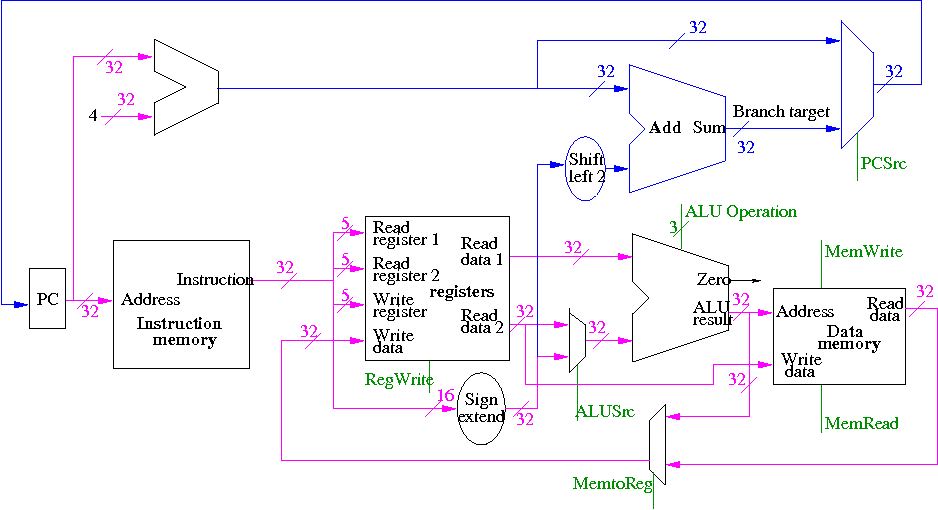
We will first put the pieces together and later figure out the control lines that are needed and how to set them. We are not now worried about speed.
We are assuming that the instruction memory and data memory are separate. So we are not permitting self modifying code. We are not showing how either memory is connected to the outside world (i.e., we are ignoring I/O).
We must use the same register file with all the pieces since when a load changes a register, a subsequent R-type instruction must see the change and when an R-type instruction makes a change, the lw/sw must see it (for loading or calculating the effective address, etc).
We could use separate ALUs for each type of instruction but we are not worried about speed so we will use the same ALU for all instruction types. We do have a separate adder for incrementing the PC.
The problem is that some inputs can come from different sources.
We will deal with the first two now by using a mux for each. We will deal with the third shortly by (surprise) using a mux.
This is quite easy
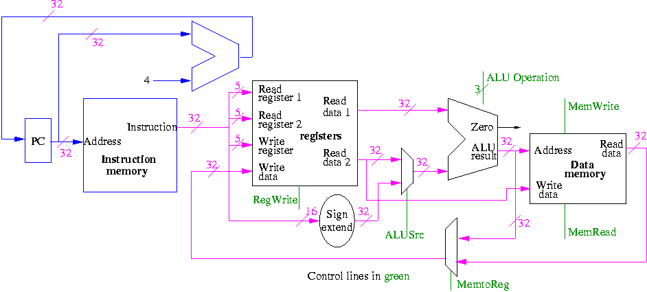
We need to have an if stmt
for PC (i.e., a mux)
Homework: Extend the datapath just constructed to support the addi instruction as well as the instructions already supported.
Homework: Extend the datapath just constructed to support a variation of the lw instruction where the effective address is computed by adding the contents of two registers (instead of using an immediate field). This new instruction would be an R-type. Continue to support all the instructions that the original datapath supported.
Homework: Can you support a hypothetical swap instruction that swaps the contents of two registers using the same building blocks that we have used to date?