Computer Architecture
Start Lecture #9
Homework: 36
SRAMS and DRAMS
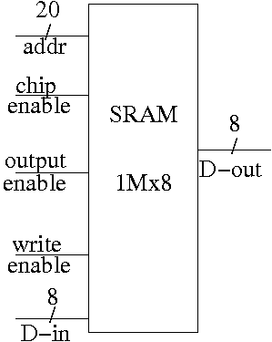
- External interface is on right
- 1Mx8 means it hold 1M (million) words each 8 bits.
- Addr, D-in, and D-out are same as they were for registers.
Addr is 20 bits since 220 = 1M.
D-out is 8 bits since we have a by 8 SRAM.
- Write enable is similar to the write line (unofficial: it
is a pulse; there is no clock),
- Output enable is for the three state (tri-state) drivers
discussed just below (unofficial).
- Ignore chip enable (perfer not to have all chips enabled
for electrical reasons).
- (Sadly) we will not look inside officially. Following is
unofficial
- Conceptually, an SRAM is like a register file but we can't
use the register file implementation for a large SRAM because
there would be too many wires and the muxes would be too big.
- We use a two stage decode.
- A 1Mx8 SRAM would need a 20-1M decoder.
- Instead the SRAM is configured internally as say thirty-two
2048x128 SRAMS.
- Pass 11 of the 20 address bits through a 11-2048
decoder and use the 2048 output wires to select the
appropriate 128-bit word from each of the sub SRAMS.
Use two of the remaining bits to select eight of the sub
SRAMS (2 bits can choose one of four 8-SRAM subsets of
the 32 sub-SRAMS).
Use the remaining 7 addr bits to select the appropriate
bit from each 128-bit word.
- Tri-state buffers (drivers) are used instead of a mux.
- I was fibbing when I said that outputs are always
either 1 or 0.
- However, we will not use tristate logic; we will use
muxes.
- DRAM uses a version of the above two stage decode.
- View the memory as an array.
- First select (and save in a
faster
memory) an
entire row.
- Then select and output only one (or a few) column(s).
- So can speed up access to elements in same row.
- SRAM and ``logic'' are made from similar technologies but
DRAM technology is quite different.
- So easy to merge SRAM and CPU on one chip (SRAM
cache).
- Merging DRAM and CPU is more difficult but is now
being done.
- Error Correction (Omitted)
Note: There are other kinds of flip-flops T, J-K.
Also one could learn about excitation tables for each.
We will not cover this material (P&H doesn't either).
If interested, see Mano.
B.6: Finite State Machines (FSMs)
More precisely, we are learning about deterministic
finite state machines or deterministic finite automata (DSA).
The alternative nondeterministic finite automata (NDA) are somewhat
strange and, althought seemingly nonrealistic and of theoretical
value only, form together with DFA, what I call the
secret weapon
used in the first stage of a compiler (the
lexical analyzer.
I do a different example from the book (counters instead of traffic
lights).
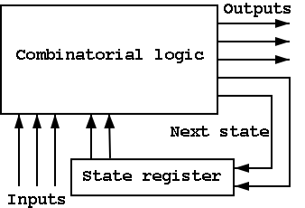
The ideas are the same and the two generic pictures (below) apply to
both examples.

Counters
A counter counts (naturally).
- The counting is done in binary.
- The circuit increments (i.e., counts) on each clock ticks
(active edge).
- Actually it increments only on those clocks ticks when
the
increment
line is asserted.
- The state has one component, the value of the counter.
Since we are starting with a 1-bit counter, there are precisely
two states.
- There are two inputs: I and R, increment and reset.
- If reset is asserted at a clock tick, the counter is reset to
zero.
- What should we do if both R and I are
asserted?
- Probably that
shouldn't happen
.
We will accept any answer in that case (i.e., don't care).
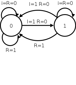
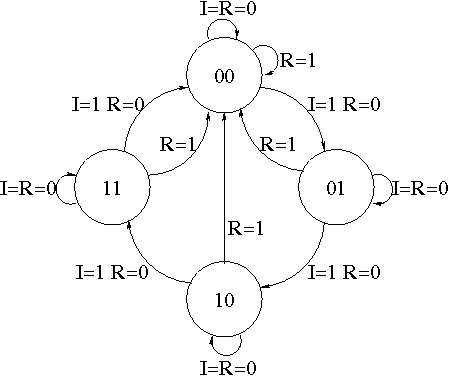
The State Transition Diagram
- The figure shows the state transition diagram for A, the output of
a 1-bit counter.
- The circles represent states; the arcs represent transitions
from one state to another.
The label on the arc gives the condition for the transition to
apply.
For example, in state 1, if R=1, we transition to state 0.
- At each state, for each possible value of the state and inputs,
the must be a transition.
- In this implementation, if R=I=1 we choose to set A to zero.
That is, if Reset and Increment are both asserted, we do the
Reset.
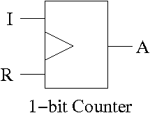
The circuit diagram.
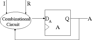
- Uses one flop and a combinatorial circuit.
- The (combinatorial) circuit is determined by the transition diagram.
- The circuit must calculate the next value of A from the current
value and I and R.
- The flop producing A is often itself called A and the D input to this
flop is then called DA.
- To fit the diagram above for FSMs, we should not draw the overall
output (A) coming from the flop (state register) but instead from the
combinational circuit (which is easy since A is input to that circuit).
Determining the combinatorial circuit
How do we determine the combinatorial circuit?
- This circuit has three inputs, I, R, and the current A.
- It has one output, DA, which is the desired next A.
- So we draw a truth table, as before.
- For convenience I added the label Next A to the DA column
Current      || Next A
   A    I R  || DA <-- i.e. to what must I set DA
-------------++--      in order to get the desired
   0    0 0  || 0      A for the next cycle.
   1    0 0  || 1
   0    1 0  || 1
   1    1 0  || 0
   x    x 1  || 0
But this table is simply the truth table for the combinatorial
circuit.
A I R  || DA
-------++--
0 0 0  || 0
1 0 0  || 1
0 1 0  || 1
1 1 0  || 0
x x 1  || 0

DA = R' (A ⊕ I)
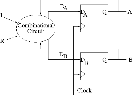
A 2-bit Counter.
No new ideas are needed; just more work.
- State diagram has 4 states 00, 01, 10, 11 and transitions from one
to another.
- The circuit diagram has 2 D-flops.
To determine the combinatorial circuit we could precede as before
  Current      ||
    A B   I R  || DA DB
  -------------++------
This would work (start it on the board), but we can instead think
about how a counter works and see that.
    DA = R'(A ⊕ I)
    DB = R'(B ⊕ AI)
A 3-bit Counter
Homework: B.39
B.7 Timing Methodologies
Skipped
Simulating Combinatorial Circuits at the Gate Level
The idea is, given a circuit diagram, write a program that behaves
the way the circuit does.
This means more than getting the same answer.
The program is to work the way the circuit does.
For each logic box, you write a procedure with the following properties.
- A parameters is defined for each input and output wire.
- A (local) variable is defined for each internal wire.
Really means a variable define for each signal. If a signal is
sent from one gate to say 3 others, you might not call all those
connections one wire, but it is one signal and is represented by
one variable
- The only operations used are AND OR XOR NOT
- In C or Java & | ^ !
- Other languages similar.
- Java is particularly well suited since it has variables and
constants of type Boolean.
- An assignment statement (with an operator) corresponds to a
gate.
For example A = B & C; would mean that there is an AND gate with
input wires B and C and output wire A.
- NO conditional assignment.
- NO if then else statements.
We know how to implement a mux using ANDs, ORs, and NOTs.
- Single assignment to each variable.
Multiple assignments would correspond to a cycle or to two outputs
connected to the same wire.
- A bus (i.e., a set of signals) is represented by an array.
- Testing
- Exhaustive possible for 1-bit cases.
- Cleverness for n-bit cases (n=32, say).
Simulating a Full Adder
Remember that a full adder has three inputs and two outputs.
Discuss FullAdder.c or perhaps
FullAdder.java.
Simulating a 4-bit Adder
This implementation uses the full adder code above.
Discuss FourBitAdder.c or perhaps
FourBitAdder.java
Chapter 1: Computer Abstractions and Technologies
Homework:
READ chapter 1. Do 1.1 -- 1.28 (really one matching question)
Do 1.29 to 1.45 (another matching question),
1.46.
Chapter 2: Instructions: Language of the Machine
Homework:
Read sections 2.1, 2.1, and 2.3 (you need not worry about how a
compiler works, but you might want to).
2.4 Representing instructions in the Computer (MIPS)
The Register File
- We just learned how to build these.
- MIPS has 32 Registers, each 32 bits.
- Register 0 is always 0 when read, and stores to register 0 are
ignored.
The fields of a MIPS instruction are quite consistent
    op    rs    rt    rd    shamt  funct   name of field
     6     5     5     5      5      6     number of bits
- op is the opcode
- rs,rt are source operands
- rd is destination
- shamt is the shift amount
- funct is used for op=0 to distinguish alu ops
- alu is arithmetic and logic unit
- add/sub/and/or/not etc.
- We will see there are other formats (but similar to this one).
R-type Instructions (R for register)
Example: add $1,$2,$3
- R-type instructions use the format above.
- The example given has for its 6 fields
0--2--3--1--0--32
- op=0, signifying an alu op.
- funct=32 specifies add.
Funct determines the control bits to the alu.
- reg1 <— reg2 + reg3
- All three register numbers can be the same (this doubles the
value in the register).
- Do sub by just changing the funct.
- If the three register numbers are the same for subtract, the
instruction clears (i.e., sets to zero) the register.