Start Lecture #7
MIPS (and most other) processors must execute shift (and rotate) instructions.
We could easily extend the ALU to do 1-bit shift/rotates (i.e., shift/rotate a 32-bit quantity by 1 bit), and then perform an n-bit shift/rotate as n 1-bit shift/rotates.
This is not done in practice. Instead a separate structure, called a barrel shifter is built outside the ALU.
Remark: Barrel shifters, like CLAs are of logarithmic complexity.
Why do we need state?
Assume you have a physical OR gate. Assume the two inputs are both zero for an hour. At time t one input becomes 1. The output will OSCILLATE for a while before settling on exactly 1. We want to be sure we don't look at the answer before its ready.
This will require us to establish a clocking methodology, i.e. an approach to determining when data is valid.
First, however, we need some ...
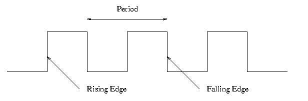
Consider the idealized waveform shown on the right. The horizontal axis is time and the vertical axis is (say) voltage.
If the waveform repeats itself indefinitely (as the one on the right does), it is called periodic.
The time required for one complete cycle, i.e., the
time between two equivalent points in consecutive cycles, is called
the period.
Since it is a time, period is measured in units such as seconds, days, nanoseconds, etc.
The rate at which cycles occur is called the frequency.
Since it is a rate at which cycles occur, frequency is measured in units such as cycles per hour, cycles per second, kilocycles per microweek, etc.
The modern (and less informative) name for cycles per second is Hertz, which is abbreviated Hz.
Prediction: At least one student will confuse frequency and periods on the midterm or final and hence mess up a gift question. Please, prove me wrong!
Make absolutely sure you understand why
Look at the diagram above and note the rising edge and the falling edge.
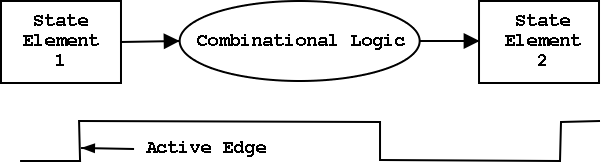
We will use edge-triggered logic, which means that state changes (i.e., writes to memory) occur at a clock edge.
For each design we choose to either
The edge on which changes occur (either the rising or falling edge) is called the active edge. For us, choosing which edge is active is basically a coin flip.
Now we are going to add state elements to the combinational circuits we have been using previously.
Remember that a combinational/combinatorial circuits has its outpus determined solely by its input, i.e. combinatorial circuits do not contain state.
State elements include state (naturally).
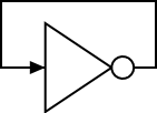
Combinatorial circuits can NOT contain
loops.
For example imagine an inverter with its output connected to its
input.
So if the input is false, the output becomes true.
But this output is wired to the input, which is now true.
Thus the output becomes false, which is the new input.
So the output becomes true ... .
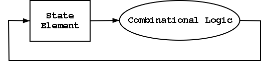 However sequential circuits CAN and
often Do contains loops.
However sequential circuits CAN and
often Do contains loops.
We will use only edge-triggered, clocked memory in our designs as they are the simplest memory to understand. So our current goal is to construct a 1-bit, edge-triggered, clocked memory cell. However, to get there we will proceed in three stages.
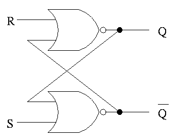
The only unclocked memory we will use is a so called S-R latch (S-R stands for Set-Reset).
When we define latch
below to be a level-sensitive, clocked
memory, we will see that the S-R latch is not really a latch.
The circuit for an S-R latch is on the right. Note the following properties.
Cross-couplednor gates.
The S-R latch defined above is UNclocked memory; unfortunately the terminology is not perfect.
For both flip-flops and latches the output equals the value stored in the structure. Both have an input and an output (and the complemented output) and a clock input as well. The clock determines when the internal value is set to the current input. For a latch, the output can change whenever the clock is asserted (level sensitive). For a flip-flop, changes occur only at the active edge.
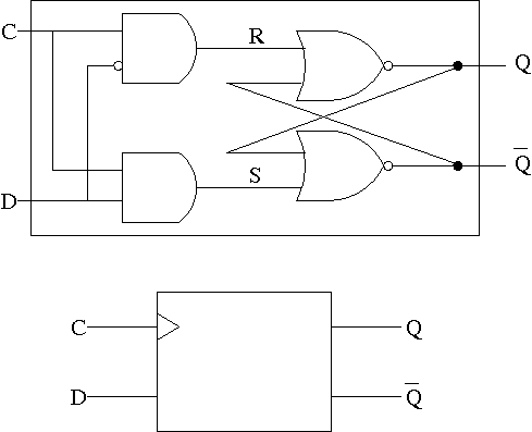
The D stands for data.
Note the following properties of the D latch circuit shown on the right.
A D latch is sometimes called a transparent latch since, whenever the clock is high, the output equals the input (the input passes right through the latch).
We won't use D latches in our designs, except right now to our workhorse, the master-slave flip-flop, an edge-triggered memory cell.
The lower diagram is how a D-latch is normally drawn.
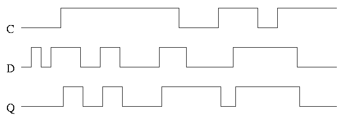
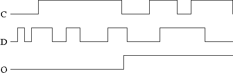
In the traces to the right notice how the output follows the input
when the clock is high and remains constant when the clock is low. We
assume the stored value was initially low.
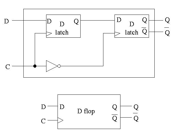
This structure was our goal. It is an edge-triggered, clocked memory.
The circuit for a D flop
is on the right has the following
properties.
Homework: Move the inverter to the other latch. What has changed?
 The picture on the right is for a master-slave flip-flop.
Note how much less wiggly the output is in this picture
than before with the transparent latch.
As before we are assuming the output is initially low.
The picture on the right is for a master-slave flip-flop.
Note how much less wiggly the output is in this picture
than before with the transparent latch.
As before we are assuming the output is initially low.
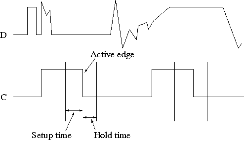 This picture shows the setup and hold times discussed above.
Homework: Which code better describes a flip-flop and which a latch?
    repeat {
       while (clock is low) {do nothing}
       Q=D
       while (clock is high) {do nothing}
    } until forever

  or

    repeat {
    while (clock is high) {Q=D}
    } until forever