Computer Architecture
Start Lecture #6
Super Propagate
and Super Generate
We start the adventure by defining ``super propagate'' and
``super generate'' bits.
- A super propagate bit indicates whether the
4-bit CLA constructed above propagates a
Carry-In to a Carry-Out.
Super propagation occurs for a 4-bit adder when each of the
constituent 1-bit adders propagates.
- A super generate bit indicates whether the
4-bit CLA constructed above generates a
Carry-Out.
Super generation occurs for a 4-bit adder when some 1-bit
adder generates and all subsequent 1-bit adders propagate.
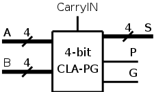
- To the right we show the P&H
plumbing
picture for
super propagate and super generate.
A larger picture is here.
- The corresponding logic formulas are as follows.
    P0 = p3 p2 p1 p0      Low order 4-bit adder propagates a carry
    P1 = p7 p6 p5 p4
    P2 = p11 p10 p9 p8
    P3 = p15 p14 p13 p12  High order 4-bit adder propagates a carry

    G0 = g3 + p3 g2 + p3 p2 g1 + p3 p2 p1 g0   Low order 4-bit adder generates a carry
    G1 = g7 + p7 g6 + p7 p6 g5 + p7 p6 p5 g4
    G2 = g11 + p11 g10 + p11 p10 g9 + p11 p10 p9 g8
    G3 = g15 + p15 g14 + p15 p14 g13 + p15 p14 p13 g12
From these super propagates and super generates, we can calculate the
super carries, i.e. the carries for the four 4-bit adders.
- The first super carry C0, the Carry-In to the low-order 4-bit
adder, is just c0 the input Carry-In.
- The second super carry C1 is the Carry-Out of the low-order
4-bit adder (which is also the Carry-In to the 2nd 4-bit adder.
- The third super carry C2 is the Carry-Out of the second 4-bit
adder (which is also the Carry-In to the 3rd 4-bit adder.
- The forth super carry C3 is the Carry-Out of the third 4-bit
adder (which is also the Carry-In to the 4th (high-order) 4-bit
adder.
- The last super carry C4 is the Carry-out of the high-order
4-bit adder (which is also the overall Carry-out of the entire
16-bit adder).
- The corresponding logic formulas are as follows.
    C1 = G0 + P0 c0
    C2 = G1 + P1 C1 = G1 + P1 G0 + P1 P0 c0
    C3 = G2 + P2 C2 = G2 + P2 G1 + P2 P1 G0 + P2 P1 P0 c0
    C4 = G3 + P3 C3 = G3 + P3 G2 + P3 P2 G1 + P3 P2 P1 G0 + P3 P2 P1 P0 c0
But this looks terrific!
These super carries are what we need to combine four 4-bit CLAs into
a 16-bit CLA in a carry-lookhead manner.
Recall that the hybrid approach suffered because the carries from
one 4-bit CLA to the next (i.e., the super carries) were done in a
ripple carry manner.
Since it is not completely clear how to combine the pieces so far
presented to get a 16-bit, 2-level CLA, I will give a pictorial
account very soon.
Before the pictures, let's assume the pieces can be put together
and see how fast the 16-bit, 2-level CLA actually is.
Recall that we have already seen two practical 16-bit adders: A
ripple carry version taking 32 gate delays and a hybrid structure
taking 14 gate delays.
If the 2-level design isn't faster than 14 gate delays, we won't
bother with the pictures.
Remember we are assuming 5-input gates.
We use lower case p, g, and c for propagates, generates, and
carries; and use capital P, G, and C for the super- versions.
- We calculate the p's and g's (lower case) in 1 gate delay (as with
the 4-bit CLA).
- We calculate the P's one gate delay after we have the p's or
2 gate delays after we start.
- The G's are determined 2 gate delays after we have the g's and
p's.
So the G's are done 3 gate delays after we start.
- The C's are determined 2 gate delays after the P's and G's. So
the C's are done 5 gate delays after we start.
- Now the C's are sent back to the 4-bit CLAs, which have already
calculated the p's and g's.
The c's are calculated in 2 more
gate delays (7 total) and the s's 2 more after that (9 total).
Since 9<14, let the pictures begin!
- First perform minor surgery on the 4-bit CLA.
- Remove the calculation of the CarryOut, as that
calculation will be performed by a different piece of logic.
- Add logic to calculate the super propagate and super
generate bits P & G using the formulas given above.
- Label the resulting structure a 4-bit CLA-PG (not a
standard name).
- CLA-PG has 9 inputs (two 4-bit addends and a carry-in) and 6
outputs (a 4-bit sum, P, and G).
- The diagram is on the right.
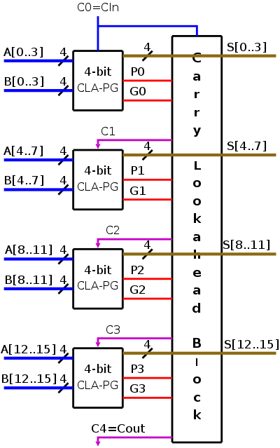
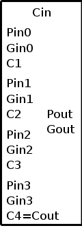
- Next put four of these 4-bit CLAs together with a Carry
Lookahead Block that calculates the C's from the P's, G's and
Cin=C0.
- The formulas for the C's are above.
- The result, which is shown on the right, is a 16-bit
(2-level) CLA!
- We will use CL Block to abbreviate Carry-Lookahead Block
(I am afraid to use CLB fearing it will be confused with
CLA).
- Note that I do not call it a 4-bit CL Block or a 16-bit CL
block.
More on this latter.
- The colors of the lines indicates when they are
calculated.
- The blue lines are inputs.
- Then the red lines are calculated.
- Then the magenta.
- Finally the brown.
- That last bullet is stated sloppily.
Gates are always calculating their
outputs from their inputs.
When we say something is calculated in k gate delays, we
mean that the outputs are correct k gate delays after the
inputs are correct.
A more accurate statement of the previous bullet would be:
- The blue lines are input, which are assumed to be
valid when we start the addition.
- The red lines are valid 3 gate delay after the blue
(actually the Ps needs only 2 gate delays, but we use
the Ps and Gs together so need to wait for the Gs).
Summary: the red lines are valid 3 gate delays after we
start
- The magenta lines are valid 2 gate delays after the
red; so they are valid 5 gate delays after the start.
- The brown lines are valid 4 gate delays after the
magenta (2 gate delays to calculate the c's—note
lower case, then two more for the Ss); so they are valid
9 gate delays after the start
- Since the magenta lines flow right to left (then down), I
drew their arrowheads.
I typically do not draw arrowheads for lines that go to the
right, go down, or go right and down.
- We actually are not done with the CL Block.
Building CLAs Using the CL Block
It is time to validate the claim that all sizes of PLAs can be
build (recursively) using the CL Block.
1-bit CLA-PG
A 1-bit CLA is just a 1-bit adder.
With only one bit there is no need for any lookahead
since
there is no ripple
to try to avoid.
However, to enable us to build a 4-bit CLA from the 1-bit version,
we actually need to build what we previously called a CLA-PG.
The 1-bit CLA-PG has three inputs a, b, and cin.
It produces 4 outputs s, cout, p, and g.
We have given the logic formulas for all four outputs previously.
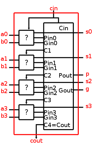
4-bit CLA-PG
A 4-bit CLA-PG is shown as the red portion in the figure to the right.
It has nine inputs: 4 a's, 4 b's, and cin and must produce seven
outputs: 4 s's, cout, p, and g (recall that the last two were
previously called the super propagate and super generate respectively).
The tall black box is our CL Block.
The question is, what must the ith ?
box do in
order for the entire (red) structure to be a 4-bit CLA-PG?
.
- The box must produce si, one bit of the desired
sum.
But this is easy since the box receives ai,
bi, and ci the carry in (c0 is cin).
- si = ai bi ci +
ai bi' ci' +
ai' bi ci' +
ai' bi' ci
- The box must produce pi and gi for the
CL Block to consume.
But that is also easy since it has as input ai and
bi.
- It looks like the ? box is just a 1-bit CLA-PG!
- Unfortunately, not quite.
The ? box is only a (large) subset of a 1-bit CLA-PG.
- What is missing?
- Ans.
The ? box doesn't need to produce a carry out since the larger
(4-bit) CLA-PG contains a Cl-block that produces all of them.
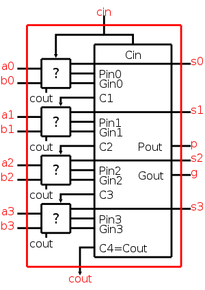
So, if we want to say that the 4-bit (1-level) CLA-PG is composed
of four 1-bit (0-level) CLA-PGs together with a CL Block, we must
draw the picture as on the right.
The difference is that we explicitly show that the ? box
produces cout, which is then not used.
This situation will occur for all sizes.
For example, either picture on the right for a a 4-bit
CLA-PG produces a carry out since all 4-bit full adders do so.
However, a 16-bit CLA-PG, built from four of the 4-bit units and a
CL Block, does not use the carry outs produced by the four 4-bit
units.
We have several alternatives.
- Don't mention the problem of the unused cout.
A common solution but too late for us.
- Draw the top version of the diagram (without the unused
cout's) and delcare that a CLA-PG doesn't produce a carry out.
Seems weird that a CLA-PG doesn't fully replace a full adder.
- Draw the top version of the diagram
and admit that a level k CLA-PG doesn't really use four level k-1
CLA-PG's.
- Draw the bottom version of the diagram.
- Draw the top version of the diagram, but view it as an
abbreviation of the bottom version.
This last is the alternative we will choose.
As another abbreviation, we will henceforth say CLA when we mean
CLA-PG.
Remark:
Hence the 4-bit CLA (meaning CLA-PG) is composed of
- Four 1-bit CLAs
- One CLA block
- Wires
- Nothing else
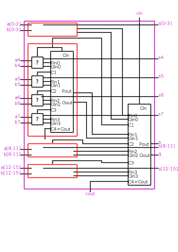
16-bit CLA-PG
Now take four of these 4-bit adders and use the
identical CL block to get a 16-bit
adder.
The picture on the right shows one 4-bit adder (the red box) in
detail.
The other three 4-bit adders are just given schematically as small
empty red boxes.
The CL block is also shown and is wired to all four 4-bit adders.
The complete (large) picture is
shown here.
Remark:
Hence the 16-bit CLA is composed of
- Four 4-bit CLAs
- One CLA block
- Wires
- Nothing else
64-bit CLA-PG
To construct a 64-bit CLA no new components are needed.
That is, the only components needed have already been constructed.
Specifically you need.
- Four magenta boxes, identical to
the one just constructed.
- One additional CL Block, identical
to the one just used to make the magenta box.
- Wires to connect these five boxes.
Remark:
Hence the 64-bit CLA (meaning CLA-PG) is composed of
- Four 16-bit CLAs
- One CLA block
- Wires
- Nothing else
When drawn (with a brown box) the 64-bit CLA-PG has 129 inputs
(64+64+1) and 67 outputs (64+1+2).
256-bit CLA-PG
- Four brown boxes, identical to
the one just constructed.
- One additional CL Block, identical
to the one just used to make the brown box.
- Wires to connect these five boxes.
Remark:
Hence the 256-bit CLA (meaning CLA-PG) is composed of
- Four 64-bit CLAs
- One CLA block
- Wires
- Nothing else
etc
Homework: How many gate delays are required for
our 64-bit CLA-PG?
How many gate delays are required for a 64-bit ripple carry adder
(constructed from 1-bit full adders)?
Summary
CLAs greatly speed up addition; the increase in speed grows with
the size of the numbers to be added.
Remark: CLAs implement n-bit addition in
O(log(n)) gate delays.