Computer Architecture
Start Lecture #5
Remark:
Lab 3 assigned.
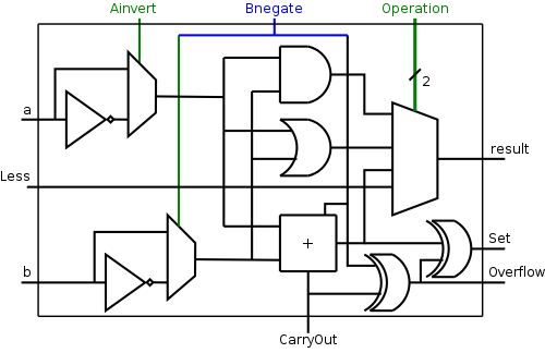
A Simple Observation
The CarryIn to the LOB and
Binvert to all the 1-bit ALUs are always
the same.
So the ALU has just one input called Bnegate, which is sent
to the appropriate inputs in the 1-bit ALUs.
The final 1-bit cell of the ALU is shown on the right.
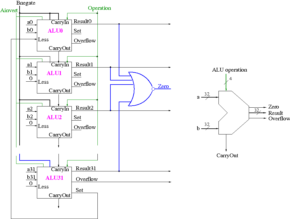
Note that the circuit is the same for all bits;
however different bits are wired differently, i.e.,
they have different inputs and their outputs are sent to different
places.
Equality Detection
To see if A = B we simply form A-B and test if
the result is zero
- To see if all the bits are zero, is just a large NOR.
- This is conceptually trivially, but does require some wiring.
The Final Result
The final 32-bit ALU is shown below on the left.
Again note that all the bits have the same circuit.
The lob and hob have special external wiring;
the other 30 bits are wired the same.
To the right of this diagram we see the symbol used for an ALU.
What are the control lines?
- Ainvert (1 bit)
- Bnegate (1 bit)
- OP (2 bits)
What functions can we perform?
| function | 4-bit cntl | Ainv | Bneg | Oper |
|---|
| AND | 0000 | 0 | 0 | 00 |
| OR | 0001 | 0 | 0 | 01 |
| ADD | 0010 | 0 | 0 | 10 |
| SUB | 0110 | 0 | 1 | 10 |
| slt | 0111 | 0 | 1 | 11 |
| NOR | 1100 | 1 | 1 | 00 |
- AND
- OR
- ADD
- SUB
- NOR
- slt (set on less than)
We think of the three control
lines Ainvert, Bnegate, and Operation as
forming a single 4-bit control line.
The table on the right shows what four bit value is needed for each
function.
Defining the MIPS ALU in Verilog
Skipped.
B.6: Faster Addition: Carry Lookahead
This adder is much faster than the ripple adder we did before,
especially for wide (i.e., many bit) addition.
Fast Carry Using Infinite
Hardware
This is a simple (theoretical) result.
- An adder is a combinatorial circuit hence it can be
constructed with two (or three if you count the bubbles) levels
of logic.
Done
- Consider 32-bit (or 64-bit, or 128-bit, or N-bit) addition, R=A+B.
- This is a logic function with 32+32+1=65 binary inputs (A, B,
and the CarryIn to the lob).
- It has 33 outputs R and the final CarryOut.
- Hence it can be expressed by a truth table having
265 rows and 65+33=98 columns.
- This is a gigantic truth table (about 3
billion trillion entries), but nonetheless finite.
- The corresponding PLA needs no more than 265
minterms feeding no more than 33 ORs.
- Since each minterm is just an AND (with some bubbles) it
is just one level of logic (or two if you count the
bubbles).
The ORs are just one level of logic, so we get a total of
two (or three).
- You could object that each minterm is the AND of a bunch
(2N+1, for N-bit addition) of inputs so perhaps shouldn't be
thought of as a single level of logic (even ignoring the
bubbles).
- The same consideration applies to the ORs, which might
have even more (22N+1) inputs.
- The above is a worst case analysis.
The actual circuit for addition is probably not quite as
bad, but still completely impractical for real 32-bit adders
- The above applied to any logic function; here are the
calculations specific for addition.
- Each of the 1-bit adders we built were fast (just a few
gate delays); the trouble was that the CarryIn to the upper
order bits took a long time to calculate.
We can calculate all the CarryIn's from the inputs a, b, and
CarryIn0 using two levels of logic.
- We use c0 for CarryIn0, c1 for
CarryIn1, c2 for CarryIn2, etc.
- c0 is an input.
- c1 = a0 b0 + a0 c0 + b0 c0
- c2 = a1 b1 + a1 c1 + b1 c1
= a1 b1 + a1 a0 b0 + a1 a0 c0 + a1 b0 c0 + b1 a0 b0
+ b1 a0 c0 + b1 b0 c0
- c3 = a2 b2 + a2 c2 + b2 c2 = ... (substitute for c2)
- etc.
Fast Carry Using the First Level of Abstraction: Propagate and Generate
At each bit position we have two input bits a and b as well as a
CarryIn input.
We now define two other bits propagate and generate
(p=ai+bi and g=aibi).
To summarize, using a subscript i to represent the bit number,
    to generate  a carry:   gi = ai bi
    to propagate a carry:   pi = ai+bi
The diagram on the right, from P&H, gives a plumbing analogue for
generate and propagate.
A full size version of the diagram
is here in pdf.
The point is that liquid enters the main pipe if
either the initial CarryIn or one of the generates is true.
The water exits the pipe at the lower left (i.e.,
there is a CarryOut for this bit position) if all the propagate
valves are open from the lowest liquid entrance to the exit.
The two diagrams in these notes are from the 2e; the colors changed
between editions.
Given the generates and propagates, we can calculate all the
carries for a 4-bit addition (recall that c0=Cin is an
input) as follows (this is the formula version of the plumbing):
    c1 = g0 + p0 c0
    c2 = g1 + p1 c1 = g1 + p1 g0 + p1 p0 c0
    c3 = g2 + p2 c2 = g2 + p2 g1 + p2 p1 g0 + p2 p1 p0 c0
    c4 = g3 + p3 c3 = g3 + p3 g2 + p3 p2 g1 + p3 p2 p1 g0 + p3 p2 p1 p0 c0
Thus we can calculate c1 ... c4 in just two additional gate delays
given the p's and g's (where we assume one gate can accept upto 5
inputs).
Since we get gi and pi after one gate delay, the total delay for
calculating all the carries is 3 (this includes c4=Carry-Out)
Each bit of the sum si can be calculated in 2 gate delays given ai,
bi, and ci.
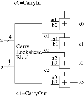
Thus, for 4-bit addition, 5 gate delays after we are given a, b and
Carry-In, we have calculated s and Carry-Out.
We show this in the diagram on the right.
- The
Carry Lookahead Block
has inputs a, and b and the
carry-in.
The block calculates the p's and g's internally (not shown in the
diagram) and then calculates the carries, which are the outputs of
the block.
The block requires 3 gate delays.
- Each small box labeled
+
is the part of a full
adder that calculates the sum
s = ai + bi + ci.
Note that the carry-out is not calculated by
this box.
The box requires 2 gate delays.
- Note the division of labor:
One block calculates the p's, g's, and carries; other logic
calculates the sum.
Thus, for 4-bit addition, 5 gate delays after we are
given a, b and Carry-In, we have calculated s and Carry-Out using a
modest amount of realistic (no more than 5-input) logic.
How does the speed of this carry-lookahead adder CLA compare to our
original ripple-carry adder?
- We have just seen that a 4-bit CLA completes its calculation
in 5 gate delays.
- The ripple-carry adder is composed of 1-bit full adders (FAs).
- Each FA needs only two gate delays.
Our design used more, but we were aiming for clarity not speed.
It is a combinatorial circuit so of course theoretically it can
be done in 2 gate delays (assuming the bubbles are free) and the
design you get in this way is practical as well.
- But the calculation of bit i takes two gate
delays starting from when the calculation of the
previous bit is finished since bit i needs the CarryOut of bit
i-1 as its own CarryIn.
- Thus the time required for a 4-bit adder is 4*2=8 gate delays.
Fast Carry Using the Second Level of Abstraction
We have finished the design of a 4-bit CLA; the next goal is a
16-bit fast adder.
Let's consider, at varying levels of detail, five possibilities.
- Ripple carry.
Simple, we know it, but not fast.
- General 2 levels of logic.
Always applicable, we know it, but not practical.
- Extend the above design to 16 bits.
Possible, we could do it, but some gates have 17 inputs.
Would need a tree to reduce the input count.
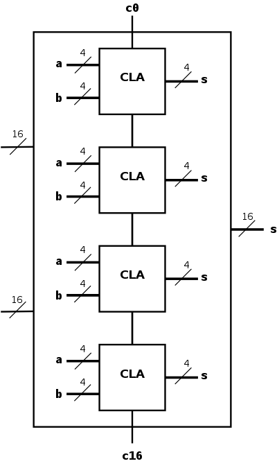
- Put together four of the 4-bit CLAs.
Shown in the diagram to the right is a schematic of our 4-bit
CLA and a 16-bit adder constructed from four of them.
- As black boxes, both ripple-carry adders and
carry-lookahead adders (CLAs) look the same.
- We could simply put four CLAs together and let the
Carry-Out from one be the Carry-In of the next.
That is, we could put these CLAs together in a ripple-carry
manner to get a hybrid 16-bit adder.
- Since the Carry-Out is calculated in 3 gate delays, the
Carry-In to the high order 4-bit adder is calculated in
3*3=9 delays.
- Hence the overall Carry-Out takes time 9+3=12 and the high
order four bits of the sum take 9+5=14.
The other bits take less time.
- So this mixed 16-bit adder takes 14 gate delays compared
with 2*16=32 for a straight ripple-carry 16-bit adder.
- Note that this hybrid structure is not a
true 16-bit CLA because the 4-bit structures are ripple-carry
connected.
- Be more clever and put together the 4-bit CLAs in a
carry-lookahead manner.
One could call the result a 2-level CLA.
- We have 33 inputs a0,...,a15; b0,...b15; c0=Carry-In
- We want 17 outputs s0,...,s15; c16=c=Carry-Out
- Again we are assuming a gate can accept upto 5 inputs.
- It is important that the number of inputs per gate does not grow
with the number of bits we are adding.
- If the technology available supplies only 4-input gates (instead
of the 5-input gates we are assuming),
we would use groups of three bits rather than four.
- This will take us some time to develop and is our next goal.