Start Lecture #2
The first way we solved the previous example shows that any logic equation can be written using just AND, OR, and NOT. Indeed it shows more. Each entry in the output column of the truth table corresponds to the AND of three (because there are three inputs) literals.
A literal is either an input variable or the negation of an input variable.
In mathematical logic such a formula is said to be in
disjunctive normal form
because it is the disjunction
(i.e., OR) of conjunctions (i.e., ANDs).
In computer architecture disjunctive normal form is called two levels of logic because it shows that any formula can be computed in by passing signals through only two logic functions, AND and then OR (assuming we are given the inputs and their compliments).
and machines.
With DM (DeMorgan's Laws) we can do quite a bit without resorting to truth tables.
For example one can ...
Homework: Show that the two expressions for E in the example above are equal.
Start to do the homework on the board.
Remark: You may ignore the references to Verilog in the text.
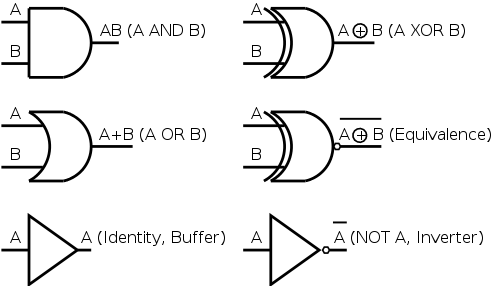
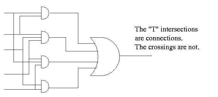
Gates implement the basic logic functions: AND OR NOT XOR Equivalence. When drawing the logic functions we use the standard shapes shown to the right for the basic logic functions.
Note that none of the figures is input-output symmetric.
That is, one can tell which lines are inputs and which are
outputs without resorting to arrowheads and without
the convention that inputs are on the left.
Sometimes the figure is rotated 90 or 180 degrees.
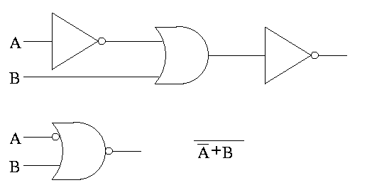
We often omit the inverters and draw the little circles at the input or output of the other gates (AND OR). These little circles are sometimes called bubbles.
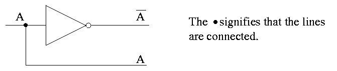
For example, the diagram on the right shows three ways a writing the same logic function.
This explains why the inverter is drawn as a buffer with an output bubble.
Show why the picture for equivalence is correct. That is, show that equivalence is the negation of XOR, i.e, show that AB + A'B' = (A ⊕ B)'.
    (A ⊕ B)' =
    (A'B+AB')' =
    (A'B)' (AB')' =
    (A''+B') (A'+B'') =
    (A + B') (A' + B) =
    (A + B') A'  +  (A + B') B =
    AA' + B'A' + AB + B'B =
    0   + B'A' + AB + 0 =
    AB + A'B'
Homework: B.4.
Homework: Recall the Boolean function E that is
true if and only if exactly 1 of the three variables is true.
We have already drawn the truth table.
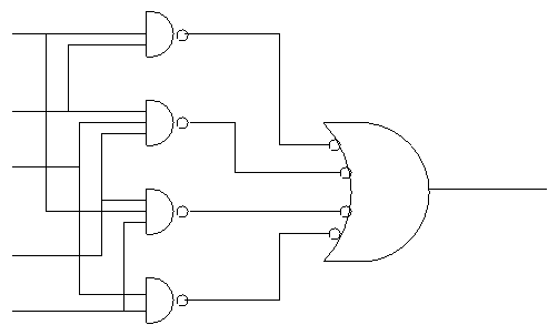
Draw a logic diagram for E using AND OR NOT.
Draw a logic diagram for E using AND OR and bubbles.
A set of gates is called universal if these gates are sufficient to generate all logic functions.
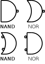
NOR (NOT OR) is true when OR is false. Draw the truth table on the board.
NAND (NOT AND) is true when AND is false. Draw the truth table on the board.
We can draw NAND and NOR each two ways as shown in the diagram on the right. The top pictures are from the definition; the bottom use DeMorgan's laws.
Theorem A 2-input NOR is universal and a 2-input NAND is universal.
Proof We will show that you can get A', A+B, and AB using just a two input NOR.
Draw the truth tables showing the last three statements.
Also say why they are correct, i.e., we are at the stage
were simple identities like these don't need truth tables.
End of Proof
Homework: Show that a 2-input NAND is universal.
Sneaky way to see that NAND is universal.
We have seen how to implement any logic function given its truth table. Indeed, the natural implementation from the truth table uses just two levels of logic. But that implementation might not be the simplest possible. That is, we may have more gates than are necessary.
Trying to minimize the number of gates is decidedly NOT trivial. A text by Mano covers the topic of gate minimization in detail. We will not cover it in this course. It is mentioned and reference, but not covered in P&H. I actually like topic but it takes a few lectures to cover well and it not used much in practice since it is algorithmic and is done automatically by CAD tools.
Minimization is not unique, i.e. there can be two or more minimal forms.
Given A'BC + ABC + ABC'
Combine first two to get BC + ABC'
Combine last two to get A'BC + AB
Sometimes when building a circuit, you don't care what the output is for certain input values. For example, that input combination might be known not to occur. Another example occurs when, for some combination of input values, a later part of the circuit will ignore the output of this part. These are called don't care outputs. Making use of don't cares can reduce the number of gates needed.
Can also have don't care inputs when, for certain values of a subset of the inputs, the output is already determined and you don't have to look at the remaining inputs. We will see a case of this very soon when we do multiplexors.
Putting a circuit in disjunctive normal form (i.e. two levels of logic) means that every path from the input to the output goes through very few gates. In fact only two, an OR and an AND. Maybe we should say three since the AND can have a NOT (bubble). Theoreticians call this number (2 or 3 in our case) the depth of the circuit. Se we see that every logic function can be implemented with small depth. But what about the width, i.e., the number of gates.
The news is bad. The parity function takes n inputs and gives TRUE if and only if the number of TRUE inputs is odd. If the depth is fixed (say limited to 3), the number of gates needed for parity is exponential in n.
Homework: Read B.3.
Generic Homework: Read sections in book
corresponding to the lectures.
Imagine you are writing a program and have 32 flags, each of which can be either true or false. You could declare 32 variables, one per flag. If permitted by the programming language, you would declare each variable to be a bit. In a language like C, without bits, you might use a single 32-bit int and play with shifts and masks to store the 32 flags in this one word.
In either case, an architect would say that you have these flags fully decoded. That is, you can detect the value of any combination of the bits.
Now imagine that for some reason you know that, at all times, exactly one of the flags is true and the other are all false. Then, instead of storing 32 bits, you could store a 5-bit integer that specifies which of the 32 flags is true. This is called fully encoded.
A 5-to-32
decoder converts an encoded 5-bit signal into 32
signals with exactly one signal true.
A 32-to-5
encoder does the reverse operations.
Note that the output of an encoder is defined
only if exactly one input bit is
set (recall set means true).
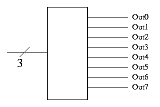
The diagram on the right shows a 3-to-8 decoder.
3with a slash, which signifies a three bit input. This notation represents three (1-bit) wires.
k written as an n-bit binary numberand view the output as 2^n bits with the k-th bit set and all the other bits clear.
Remark: Lab1 Assigned, due 17 September 2007.
Demo logisim.
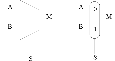
A multiplexor, often called a mux or a selector is used to select one (output) signal from a group of (input) signals based on the value of a group of (select) signals. In the 2-input mux shown on the right, the select line S is thought of as an integer 0..1. If the integer has value j then the jth input is sent to the output.
Construct on the board an equivalent circuit with ANDs and ORs in two ways: