Operating Systems
================ Start of Lectures #11 and #12 ================
Lecture 11 was given by Prof. Ernie davis. It covered material from
the next chapter.
================ Start Lecture #12 ================
4.8: Segmentation
Up to now, the virtual address space has been contiguous.
-
Among other issues this makes memory management difficult when
there are more that two dynamically growing regions.
-
With two regions you start them on opposite sides of the virtual
space as we did before.
-
Better is to have many virtual address spaces each starting at
zero.
-
This split up is user visible.
-
Without segmentation (equivalently said with just one segment) all
procedures are packed together so if one changes in size all the
virtual addresses following are changed and the program must be
re-linked. With each procedure in a separate segment this
relinking would be limited to the symbols defined or used in the
modified procedure.
-
Eases flexible protection and sharing (share a segment).
For example, can have a shared library.
Homework: 37.
** Two Segments
Late PDP-10s and TOPS-10
-
One shared text segment, that can also contain shared
(normally read only) data.
-
One (private) writable data segment.
-
Permission bits on each segment.
-
Which kind of segment is better to evict?
-
Swapping out the shared segment hurts many tasks.
-
The shared segment is read only (probably) so no writeback
is needed.
-
“One segment” is OS/MVT done above.
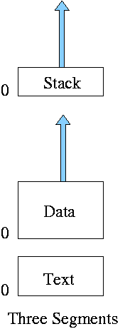
** Three Segments
Traditional (early) Unix shown at right.
-
Shared text marked execute only.
-
Data segment (global and static variables).
-
Stack segment (automatic variables).
-
In reality, since the text doesn't grow, this was sometimes
treated as 2 segments by combining text and data into one segment
** Four Segments
Just kidding.
** General (not necessarily demand) Segmentation
-
Permits fine grained sharing and protection. For a simple example
can share the text segment in early unix.
-
Visible division of program.
-
Variable size segments.
-
Virtual Address = (seg#, offset).
-
Does not mandate how stored in memory.
-
One possibility is that the entire program must be in memory
in order to run it.
Use whole process swapping.
Early versions of Unix did this.
-
Can also implement demand segmentation.
-
Can combine with demand paging (done below).
-
Requires a segment table with a base and limit value for each
segment. Similar to a page table. Why is there no limit value in a
page table?
Ans: All pages are the same size so the limit is obvious.
-
Entries are called STEs, Segment Table Entries.
-
(seg#, offset) --> if (offset<limit) base+offset else error.
-
Segmentation exhibits external fragmentation, just as whole program
swapping.
Since segments are smaller than programs (several segments make up one
program), the external fragmentation is not as bad.
** Demand Segmentation
Same idea as demand paging, but applied to segments.
-
If a segment is loaded, base and limit are stored in the STE and
the valid bit is set in the STE.
-
The STE is accessed for each memory reference (not really, TLB).
-
If the segment is not loaded, the valid bit is unset.
The base and limit as well as the disk
address of the segment is stored in the an OS table.
-
A reference to a non-loaded segment generate a segment fault
(analogous to page fault).
-
To load a segment, we must solve both the placement question and the
replacement question (for demand paging, there is no placement question).
-
I believe demand segmentation was once implemented by Burroughs,
but am not sure.
It is not used in modern systems.
The following table mostly from Tanenbaum compares demand
paging with demand segmentation.
| Consideration |
Demand
Paging | Demand
Segmentation |
|---|
| Programmer aware |
No | Yes |
| How many addr spaces |
1 | Many |
| VA size > PA size |
Yes | Yes |
Protect individual
procedures separately |
No | Yes |
Accommodate elements
with changing sizes |
No | Yes |
| Ease user sharing |
No | Yes |
| Why invented |
let the VA size
exceed the PA size |
Sharing, Protection,
independent addr spaces |
|
| Internal fragmentation |
Yes | No, in principle |
| External fragmentation |
No | Yes |
| Placement question |
No | Yes |
| Replacement question |
Yes | Yes |
** 4.8.2 and 4.8.3: Segmentation With (demand) Paging
(Tanenbaum gives two sections to explain the differences between
Multics and the Intel Pentium. These notes cover what is common to
all segmentation+paging systems).
Combines both segmentation and demand paging to get advantages of
both at a cost in complexity. This is very common now.
Although it is possible to combine segmentation with non-demand
paging, I do not know of any system that did this.
-
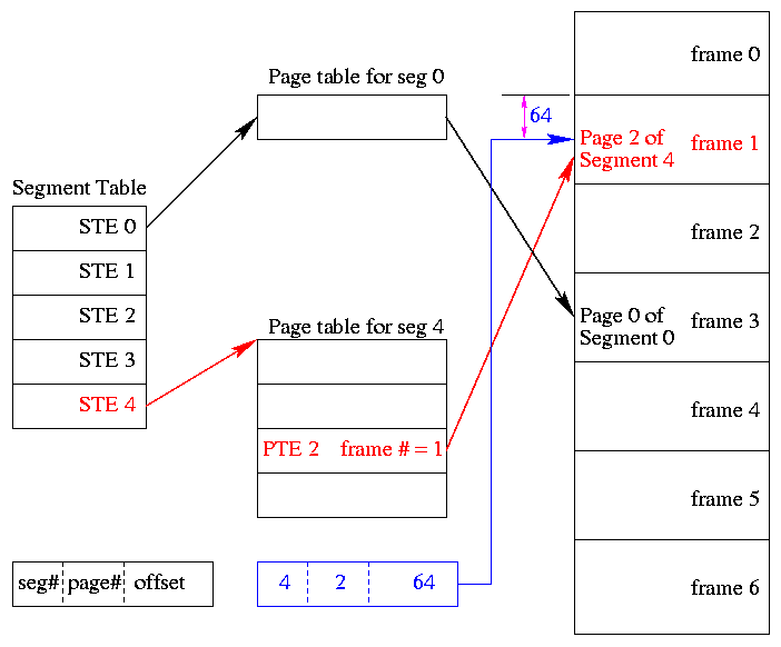
A virtual address becomes a triple: (seg#, page#, offset).
-
Each segment table entry (STE) points to the page table for that
segment.
Compare this with a
multilevel page table.
-
The physical size of each segment is a multiple of the page size
(since the segment consists of pages). The logical size is not;
instead we keep the exact size in the STE (limit value) and terminate
the process if it referenced beyond the limit. In this case the
last page of each segment is partially valid (internal
fragmentation).
-
The page# field in the address gives the entry in the chosen page
table and the offset gives the offset in the page.
-
From the limit field, one can easily compute the size of the
segment in pages (which equals the size of the corresponding page
table in PTEs).
-
A straightforward implementation of segmentation with paging
would requires 3 memory references (STE, PTE, referenced word) so a
TLB is crucial.
-
Some books carelessly say that segments are of fixed size. This
is wrong. They are of variable size with a fixed maximum and with
the requirement that the physical size of a segment is a multiple
of the page size.
-
The first example of segmentation with paging was Multics.
-
Keep protection and sharing information on segments.
This works well for a number of reasons.
-
A segment is variable size.
-
Segments and their boundaries are user (i.e., linker) visible.
-
Segments are shared by sharing their page tables. This
eliminates the problem mentioned above with
shared pages.
-
Since we have paging, there is no placement question and
no external fragmentation.
-
Do fetch-on-demand with pages (i.e., do demand paging).
-
In general, segmentation with demand paging works well and is
widely used. The only problems are the complexity and the resulting 3
memory references for each user memory reference. The complexity is
real, but can be managed. The three memory references would be fatal
were it not for TLBs, which considerably ameliorate the problem. TLBs
have high hit rates and for a TLB hit there is essentially no penalty.
Homework: 38.
Homework: Consider a 32-bit address machine using
paging with 8KB pages and 4 byte PTEs. How many bits are used for
the offset and what is the size of the largest page table?
Repeat the question for 128KB pages.
So far this question has been asked before.
Repeat both parts assuming the system also has segmentation with at most 128
segments.
4.9: Research on Memory Management
Skipped
4.10: Summary
Read
Some Last Words on Memory Management
-
Segmentation / Paging / Demand Loading (fetch-on-demand)
-
Each is a yes or no alternative.
-
Gives 8 possibilities.
-
Placement and Replacement.
-
Internal and External Fragmentation.
-
Page Size and locality of reference.
-
Multiprogramming level and medium term scheduling.
================ Start Lecture #11 ================
Chapter 5: Input/Output
5.1: Principles of I/O Hardware
5.1.1: I/O Devices
-
Not much to say. Devices are varied.
-
Block versus character devices.
This used to be a big deal, but now is of lesser importance.
-
Devices, such as disks and CDROMs, with addressable chunks
(sectors in this case) are called block
devices,
These devices support seeking.
-
Devices, such as Ethernet and modem connections, that are a
stream of characters are called character
devices.
These devices do not support seeking.
-
Some cases, like tapes, are not so clear.
-
More natural is to distinguish between
-
Input only (keyboard, mouse), vs. output only (monitor), vs.
input-output (disk).
-
Local vs. remote (network).
-
Weird (clock).
-
Random vs sequential access.
5.1.2: Device Controllers
These are the “devices” as far as the OS is concerned. That
is, the OS code is written with the controller spec in hand not with
the device spec.
-
Also called adaptors.
-
The controller abstracts away some of the low level features of
the device.
-
For disks, the controller does error checking and buffering.
-
(Unofficial) In the old days it handled interleaving of sectors.
(Sectors are interleaved if the
controller or CPU cannot handle the data rate and would otherwise have
to wait a full revolution. This is not a concern with modern systems
since the electronics have increased in speed faster than the
devices.)
-
For analog monitors (CRTs) the controller does
a great deal. Analog video is very far from a bunch of ones and
zeros.
5.1.3: Memory-Mapped I/O
Think of a disk controller and a read request. The goal is to copy
data from the disk to some portion of the central memory. How do we
do this?
-
The controller contains a microprocessor and memory and is
connected to the disk (by a cable).
-
When the controller asks the disk to read a sector, the contents
come to the controller via the cable and are stored by the controller
in its memory.
-
Two questions are: how does the OS, which is running on another
processor, let the controller know that a disk read is desired, and how
is the data eventually moved from the controller's memory to the
general system memory.
-
Typically the interface the OS sees consists of some device
registers located on the controller.
-
These are memory locations into which the OS writes
information such as the sector to access, read vs. write, length,
where in system memory to put the data (for a read) or from where
to take the data (for a write).
-
There is also typically a device register that acts as a
“go button”.
-
There are also devices registers that the OS reads, such as
status of the controller, errors found, etc.
-
So the first question becomes, how does the OS read and write the device
register.
-
With Memory-mapped I/O the device registers
appear as normal memory.
All that is needed is to know at which
address each device regester appears.
Then the OS uses normal
load and store instructions to write the registers.
-
Some systems instead have a special “I/O space” into which
the registers are mapped and require the use of special I/O space
instructions to accomplish the load and store.
-
From a conceptual point of view there is no difference between
the two models.
5.1.4: Direct Memory Access (DMA)
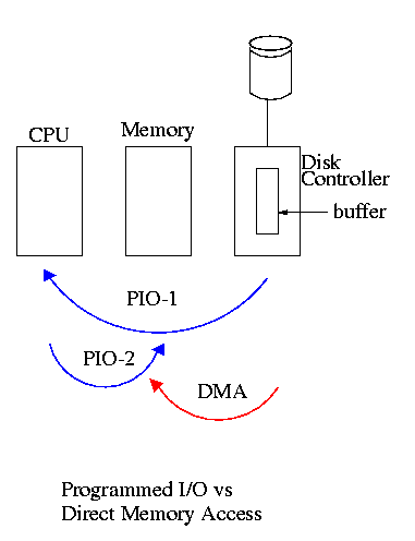
We now address the second question, moving data between the
controller and the main memory.
-
With or without DMA, the disk controller, when processing a read
request pulls the desired data from the disk to its buffer (and
pushes data from the buffer to the disk when processing a write).
-
Without DMA, i.e., with programmed I/O (PIO), the
cpu then does loads and stores (assuming the controller buffer is
memory mapped, or uses I/O instructions if it is not) to copy the data
from the buffer to the desired memory location.
-
With a DMA controller, the controller writes the main
memory itself, without intervention of the CPU.
-
Clearly DMA saves CPU work. But this might not be important if
the CPU is limited by the memory or by system buses.
-
An important point is that there is less data movement with DMA so
the buses are used less and the entire operation takes less time.
-
Since PIO is pure software it is easier to change, which is an
advantage.
-
DMA does need a number of bus transfers from the CPU to the
controller to specify the DMA. So DMA is most effective for large
transfers where the setup is amortized.
-
Why have the buffer? Why not just go from the disk straight to
the memory.
Answer: Speed matching. The disk supplies data at a fixed rate,
which might exceed the rate the memory can accept it.
In particular the memory
might be busy servicing a request from the processor or from another
DMA controller.
Homework: 12
5.1.5: Interrupts Revisited
Skipped.
5.2: Principles of I/O Software
As with any large software system, good design and layering is
important.
5.2.1: Goals of the I/O Software
Device independence
We want to have most of the OS, unaware of the characteristics of
the specific devices attached to the system.
(This principle of device independence is not limited to I/O; we also
want the OS to be largely unaware of the CPU type itself.)
This works quite well for files stored on various devices.
Most of the OS, including the file system code, and most applications
can read or write a file without knowing if the file is stored on a
floppy disk, a hard disk, a tape, or (for reading) a CD-ROM.
This principle also applies for user programs reading or writing
streams.
A program reading from ``standard input'', which is normally the
user's keyboard can be told to instead read from a disk file with no
change to the application program.
Similarly, ``standard output'' can be redirected to a disk file.
However, the low-level OS code dealing with disks is rather different
from that dealing keyboards and (character-oriented) terminals.
One can say that device independence permits programs to be
implemented as if they will read and write generic devices, with the
actual devices specified at run time.
Although writing to a disk has differences from writing to a terminal,
Unix cp, DOS copy, and many programs we write need not
be aware of these differences.
However, there are devices that really are special.
The graphics interface to a monitor (that is, the graphics interface
presented by the video controller--often called a ``video card'')
does not resemble the ``stream of bytes'' we see for disk files.
Homework: 9
Uniform naming
Recall that we discussed the value
of the name space implemented by file systems. There is no dependence
between the name of the file and the device on which it is stored. So
a file called IAmStoredOnAHardDisk might well be stored on a floppy disk.
Error handling
There are several aspects to error handling including: detection,
correction (if possible) and reporting.
-
Detection should be done as close to where the error occurred as
possible before more damage is done (fault containment). This is not
trivial.
-
Correction is sometimes easy, for example ECC memory does this
automatically (but the OS wants to know about the error so that it can
schedule replacement of the faulty chips before unrecoverable double
errors occur).
Other easy cases include successful retries for failed ethernet
transmissions. In this example, while logging is appropriate, it is
quite reasonable for no action to be taken.
-
Error reporting tends to be awful. The trouble is that the error
occurs at a low level but by the time it is reported the
context is lost. Unix/Linux in particular is horrible in this area.
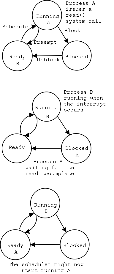
Creating the illusion of synchronous I/O
-
I/O must be asynchronous for good performance. That is
the OS cannot simply wait for an I/O to complete. Instead, it
proceeds with other activities and responds to the notification when
the I/O has finished.
-
Users (mostly) want no part of this. The code sequence
        Read X
        Y <-- X+1
        Print Y
should print a value one greater than that read. But if the
assignment is performed before the read completes, the wrong value is
assigned.
-
Performance junkies sometimes do want the asynchrony so that they
can have another portion of their program executed while the I/O is
underway. That is they implement a mini-scheduler in their
application code.
Buffering
-
Often needed to hold data for examination prior to sending it to
its desired destination.
-
But this involves copying and takes time.
-
Modern systems try to avoid as much buffering as possible. This
is especially noticeable in network transmissions, where the data
could conceivably be copied many times.
-
User space --> kernel space as part of the write system call
-
kernel space to kernel I/O buffer.
-
I/O buffer to buffer on the network adapter/controller.
-
From adapter on the source to adapter on the destination.
-
From adapter to I/O buffer.
-
From I/O buffer to kernel space.
-
From kernel space to user space as part of the read system call.
-
I am not sure if any systems actually do all seven.
Sharable vs dedicated devices
For devices like printers and tape drives, only one user at a time
is permitted. These are called serially reusable
devices, and were studied in the deadlocks chapter.
Devices like disks and Ethernet ports can be shared by processes
running concurrently.
5.2.2: Programmed I/O
-
As mentioned just above, with programmed I/O
the processor moves the data between memory and the device.
-
How does the process know when the device is ready to accept or
supply new data?
-
In the simplest implementation, the processor loops continually
asking the device. This is called polling or
busy waiting.
-
If we poll infrequently, there can be a significant delay between
when the I/O is complete and the OS uses the data or supplies new
data.
-
If we poll frequently and the device is (sometimes) slow, polling
is clearly wasteful, which leads us to ...
5.2.3: Interrupt-Driven (Programmed) I/O
-
The device interrupts the processor when it is ready.
-
An interrupt service routine then initiates transfer of the next
datum.
-
Normally better than polling, but not always. Interrupts are
expensive on modern machines.
-
To minimize interrupts, better controllers often employ ...
5.2.4: I/O Using DMA
-
We discussed DMA above.
-
An additional advantage of dma, not mentioned above, is that the
processor is interrupted only at the end of a command not after
each datum is transferred.
-
Many devices receive a character at a time, but with a dma
controller, an interrupt occurs only after a buffer has been
transferred.
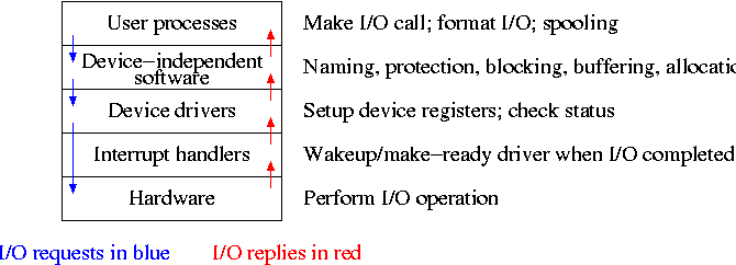
5.3: I/O Software Layers
Layers of abstraction as usual prove to be effective. Most systems
are believed to use the following layers (but for many systems, the OS
code is not available for inspection).
-
User-level I/O routines.
-
Device-independent (kernel-level) I/O software.
-
Device drivers.
-
Interrupt handlers.
We will give a bottom up explanation.
5.3.1: Interrupt Handlers
We discussed an interrupt handler before when studying page faults.
Then it was called “assembly language code”.
In the present case, we have a process blocked on I/O and the I/O
event has just completed. So the goal is to make the process ready.
Possible methods are.
-
Releasing a semaphore on which the process is waiting.
-
Sending a message to the process.
-
Inserting the process table entry onto the ready list.
Once the process is ready, it is up to the scheduler to decide when
it should run.
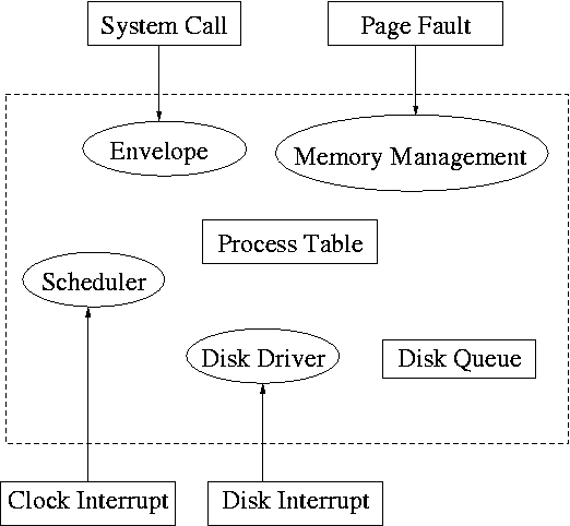
5.3.2: Device Drivers
The portion of the OS that is tailored to the characteristics of the
controller.
The driver has two “parts” corresponding to its two
access points.
Recall the figure on the right, which we saw at the
beginning of the course.
-
Accessed by the main line OS via the envelope in response to an
I/O system call. The portion of the driver accessed in this way
is sometimes call the “top” part.
-
Accessed by the interrupt handler when the I/O completes (this
completion is signaled by an interrupt). The portion of the
driver accessed in this way is sometimes call the “bottom”
part.
Tanenbaum describes the actions of the driver assuming it is
implemented as a process (which he recommends).
I give both that view
point and the self-service paradigm in which the driver is invoked by
the OS acting in behalf of a user process (more precisely the process
shifts into kernel mode).
Driver in a self-service paradigm
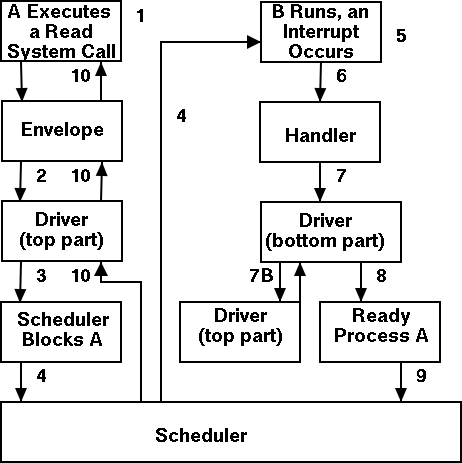
-
The user (A) issues an I/O system call.
-
The main line, machine independent, OS prepares a
generic request for the driver and calls (the top part of)
the driver.
-
If the driver was idle (i.e., the controller was idle), the
driver writes device registers on the controller ending with a
command for the controller to begin the actual I/O.
-
If the controller was busy (doing work the driver gave it
previously), the driver simply queues the current request (the
driver dequeues this request below).
-
The driver jumps to the scheduler indicating that the current
process should be blocked.
-
The scheduler blocks A and runs (say) B.
-
B starts running.
-
An interrupt arrives (i.e., an I/O has been completed) and the
handler is invoked.
-
The interrupt handler invokes (the bottom part of) the driver.
-
The driver informs the main line perhaps passing data and
surely passing status (error, OK).
-
The top part is called to start another I/O if the queue is
nonempty. We know the controller is free. Why?
Answer: We just received an interrupt saying so.
-
The driver jumps to the scheduler indicating that process A should
be made ready.
-
The scheduler picks a ready process to run. Assume it picks A.
-
A resumes in the driver, which returns to the main line, which
returns to the user code.
Driver as a process (Tanenbaum) (less detailed than above)
-
The user issues an I/O request. The main line OS prepares a
generic request (e.g. read, not read using Buslogic BT-958 SCSI controller)
for the driver and the driver is awakened (perhaps a message is sent to
the driver to do both jobs).
- The driver wakes up.
- If the driver was idle (i.e., the controller is idle), the
driver writes device registers on the controller ending with a
command for the controller to begin the actual I/O.
- If the controller is busy (doing work the driver gave it), the
driver simply queues the current request (the driver dequeues this
below).
- The driver blocks waiting for an interrupt or for more
requests.
-
An interrupt arrives (i.e., an I/O has been completed).
- The driver wakes up.
- The driver informs the main line perhaps passing data and
surely passing status (error, OK).
- The driver finds the next work item or blocks.
- If the queue of requests is non-empty, dequeue one and
proceed as if just received a request from the main line.
- If queue is empty, the driver blocks waiting for an
interrupt or a request from the main line.
5.3.3: Device-Independent I/O Software
The device-independent code does most of the functionality, but not
necessarily most of the code since there can be many drivers,
all doing essentially the same thing in slightly different ways due to
slightly different controllers.
-
Naming. Again an important O/S functionality.
Must offer a consistent interface to the device drivers.
-
In Unix this is done by associating each device with a
(special) file in the /dev directory.
-
The i-nodes for these files contain an indication that these
are special files and also contain so called major and minor
device numbers.
-
The major device number gives the number of the driver.
(These numbers are rather ad hoc, they correspond to the position
of the function pointer to the driver in a table of function
pointers.)
-
The minor number indicates for which device (e.g., which scsi
cdrom drive) the request is intended
-
Protection. A wide range of possibilities are
actually done in real systems. Including both extreme examples of
everything is permitted and nothing is permitted (directly).
-
In ms-dos any process can write to any file. Presumably, our
offensive nuclear missile launchers do not run dos.
-
In IBM and other mainframe OS's, normal processors do not
access devices. Indeed the main CPU doesn't issue the I/O
requests. Instead an I/O channel is used and the mainline
constructs a channel program and tells the channel to invoke it.
-
Unix uses normal rwx bits on files in /dev (I don't believe x
is used).
-
Buffering is necessary since requests come in a
size specified by the user and data is delivered in a size specified
by the device.
-
Enforce exclusive access for non-shared devices
like tapes.
5.3.4: User-Space Software
A good deal of I/O code is actually executed by unprivileged code
running in user space.
Some of this code consists of library routines linked into user programs,
some are standard utilities,
and some is in daemon processes.
-
Some library routines are trivial and just move their arguments
into the correct place (e.g., a specific register) and then issue a
trap to the correct system call to do the real work.
-
Some, notably standard I/O (stdio) in Unix, are definitely not
trivial. For example consider the formatting of floating point
numbers done in printf and the reverse operation done in scanf.
-
Printing to a local printer is often performed in part by a
regular program (lpr in Unix) and part by a
daemon (lpd in Unix).
The daemon might be started when the system boots.
-
Printing uses spooling, i.e., the file to be
printed is copied somewhere by lpr and then the daemon works with this
copy. Mail uses a similar technique (but generally it is called
queuing, not spooling).
Homework: 10, 13.
5.4: Disks
The ideal storage device is
-
Fast
-
Big (in capacity)
-
Cheap
-
Impossible
When compared to central memory, disks are big and cheap, but slow.
================ Continuation of Lecture #12 ================
5.4.1: Disk Hardware
Show a real disk opened up and illustrate the components.
-
Platter
-
Surface
-
Head
-
Track
-
Sector
-
Cylinder
-
Seek time
-
Rotational latency
-
Transfer rate
================ Continuation of Lecture #11 ================
Consider the following characteristics of a disk.
-
RPM (revolutions per minute)
-
Seek time. This is actually quite complicated to calculate since
you have to worry about, acceleration, travel time, deceleration,
and "settling time".
-
Rotational latency. The average value is the time for
(approximately) one half a revolution.
-
Transfer rate, determined by RPM and bit density.
-
Sectors per track, determined by bit density
-
Tracks per surface (i.e., number of cylinders), determined by bit
density.
-
Tracks per cylinder (i.e, the number of surfaces)
Overlapping I/O operations is important. Many controllers can do
overlapped seeks, i.e. issue a seek to one disk while another is
already seeking.
As technology increases the space taken to store a bit decreases,
i.e.. the bit density increases.
This changes the number of cylinders per inch of radius (the cylinders
are closer together) and the number of bits per inch along a given track.
(Unofficial) Modern disks cheat and have more sectors on outer
cylinders as on inner one. For this course, however, we assume the
number of sectors/track is constant. Thus for us there are fewer bits
per inch on outer sectors and the transfer rate is the same for all
cylinders. The modern disks have electronics and software (firmware)
that hides the cheat and gives the illusion of the same number of
sectors on all tracks.
(Unofficial) Despite what tanenbaum says later, it is not true that
when one head is reading from cylinder C, all the heads can read from
cylinder C with no penalty. It is, however, true that the penalty is
very small.
Choice of block size
-
We discussed a similar question before when studying page size.
-
Current commodity disk characteristics (not for laptops) result in
about 15ms to transfer the first byte and 10K bytes per ms for
subsequent bytes (if contiguous).
-
Rotation rate often 5400 or 7200 RPM with 10k, 15k and (just
now) 20k available.
-
Recall that 6000 RPM is 100 rev/sec or one rev
per 10ms. So half a rev (the average time to rotate to a
given point) is 5ms.
-
Transfer rates around 10MB/sec = 10KB/ms.
-
Seek time around 10ms.
-
This analysis suggests large blocks, 100KB or more.
-
But the internal fragmentation would be severe since many files
are small.
-
Typical block sizes are 4KB-8KB.
-
Multiple block sizes have been tried (e.g. blocks are 8K but a
file can also have “fragments” that are a fraction of
a block, say 1K)
-
Some systems employ techniques to force consecutive blocks of a
given file near each other,
preferably contiguous. Also some
systems try to cluster “related” files (e.g., files in the
same directory).
================ Continuation of Lecture #12 ================
Homework:
Consider a disk with an average seek time of 10ms, an average
rotational latency of 5ms, and a transfer rate of 10MB/sec.
-
If the block size is 1KB, how long would it take to read a block?
-
If the block size is 100KB, how long would it take to read a
block?
-
If the goal is to read 1K, a 1KB block size is better as the
remaining 99KB are wasted. If the goal is to read 100KB, the
100KB block size is better since the 1KB block size needs 100
seeks and 100 rotational latencies. What is the minimum size
request for which a disk with a 100KB block size would complete
faster than one with a 1KB block size?
================ Continuation of Lecture #11 ================
RAID (Redundant Array of Inexpensive Disks)
-
The name RAID is from Berkeley.
-
IBM changed the name to Redundant Array of Independent
Disks. I wonder why?
-
A simple form is mirroring, where two disks contain the
same data.
-
Another simple form is striping (interleaving) where consecutive
blocks are spread across multiple disks. This helps bandwidth, but is
not redundant. Thus it shouldn't be called RAID, but it sometimes is.
-
One of the normal RAID methods is to have N (say 4) data disks and one
parity disk. Data is striped across the data disks and the bitwise
parity of these sectors is written in the corresponding sector of the
parity disk.
-
On a read if the block is bad (e.g., if the entire disk is bad or
even missing), the system automatically reads the other blocks in the
stripe and the parity block in the stripe. Then the missing block is
just the bitwise exclusive or of all these blocks.
-
For reads this is very good. The failure free case has no penalty
(beyond the space overhead of the parity disk). The error case
requires N-1+1=N (say 5) reads.
-
A serious concern is the small write problem. Writing a sector
requires 4 I/O. Read the old data sector, compute the change, read
the parity, compute the new parity, write the new parity and the new
data sector. Hence one sector I/O became 4, which is a 300% penalty.
-
Writing a full stripe is not bad. Compute the parity of the N
(say 4) data sectors to be written and then write the data sectors and
the parity sector. Thus 4 sector I/Os become 5, which is only a 25%
penalty and is smaller for larger N, i.e., larger stripes.
-
A variation is to rotate the parity. That is, for some stripes
disk 1 has the parity, for others disk 2, etc. The purpose is to not
have a single parity disk since that disk is needed for all small
writes and could become a point of contention.
================ Continuation of Lecture #12 ================
5.4.2: Disk Formatting
Skipped.
5.4.3: Disk Arm Scheduling Algorithms
There are three components to disk response time: seek, rotational
latency, and transfer time. Disk arm scheduling is concerned with
minimizing seek time by reordering the requests.
These algorithms are relevant only if there are several I/O
requests pending. For many PCs this is not the case. For most
commercial applications, I/O is crucial and there are often many
requests pending.
-
FCFS (First Come First Served): Simple but has long delays.
-
Pick: Same as FCFS but pick up requests for cylinders that are
passed on the way to the next FCFS request.
-
SSTF or SSF (Shortest Seek (Time) First): Greedy algorithm. Can
starve requests for outer cylinders and almost always favors middle
requests.
-
Scan (Look, Elevator): The method used by an old fashioned
jukebox (remember “Happy Days”) and by elevators. The disk arm
proceeds in one direction picking up all requests until there are no
more requests in this direction at which point it goes back the other
direction. This favors requests in the middle, but can't starve any
requests.
-
C-Scan (C-look, Circular Scan/Look): Similar to Scan but only
service requests when moving in one direction. When going in the
other direction, go directly to the furthest away request. This
doesn't favor any spot on the disk. Indeed, it treats the cylinders
as though they were a clock, i.e. after the highest numbered cylinder
comes cylinder 0.
-
N-step Scan: This is what the natural implementation of Scan
gives.
-
While the disk is servicing a Scan direction, the controller
gathers up new requests and sorts them.
-
At the end of the current sweep, the new list becomes the next
sweep.
-
Compare this to selfish round robin (SRR)
with b≥a=0.