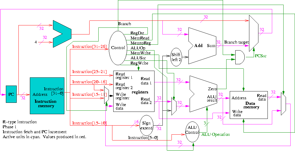
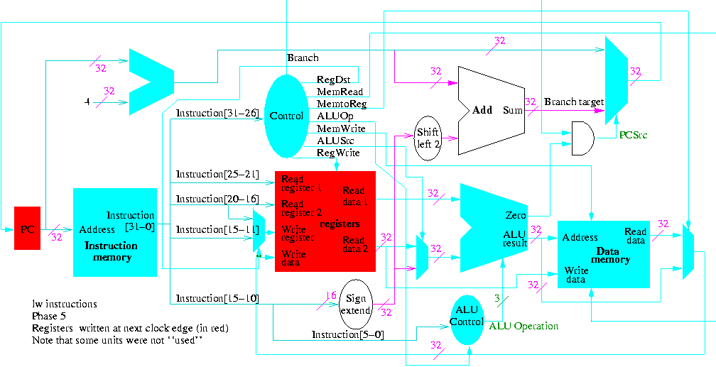
The following figures illustrate the play.
We start with R-type instructions

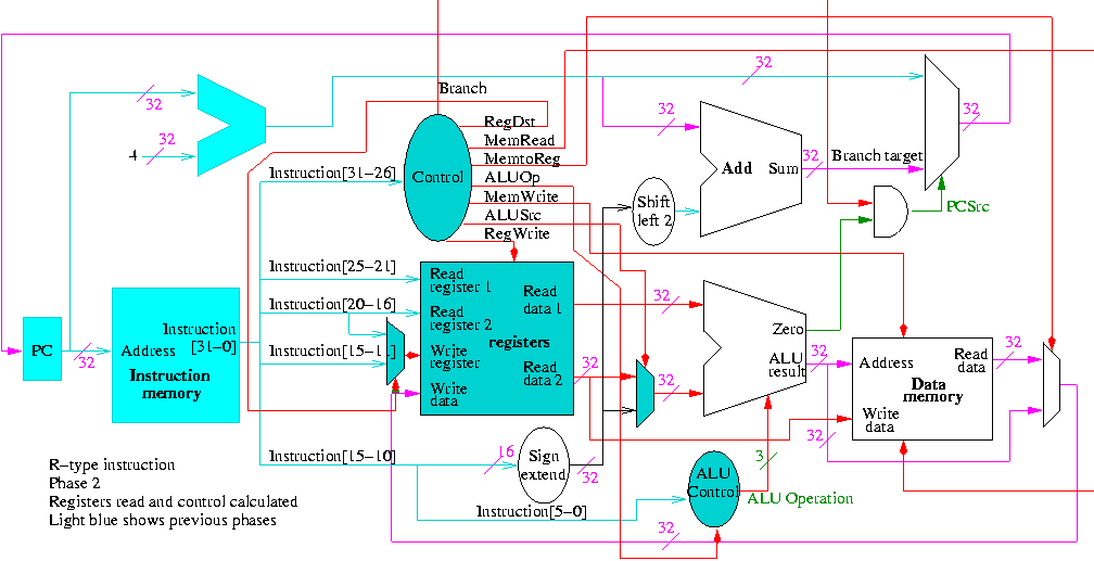
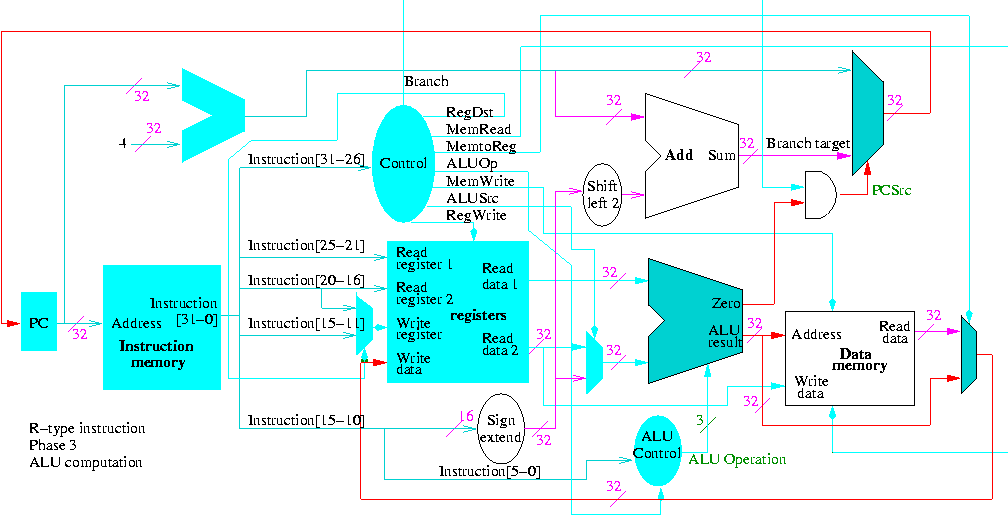
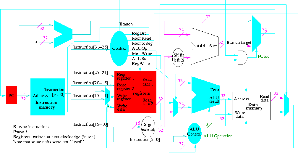
Next we show lw
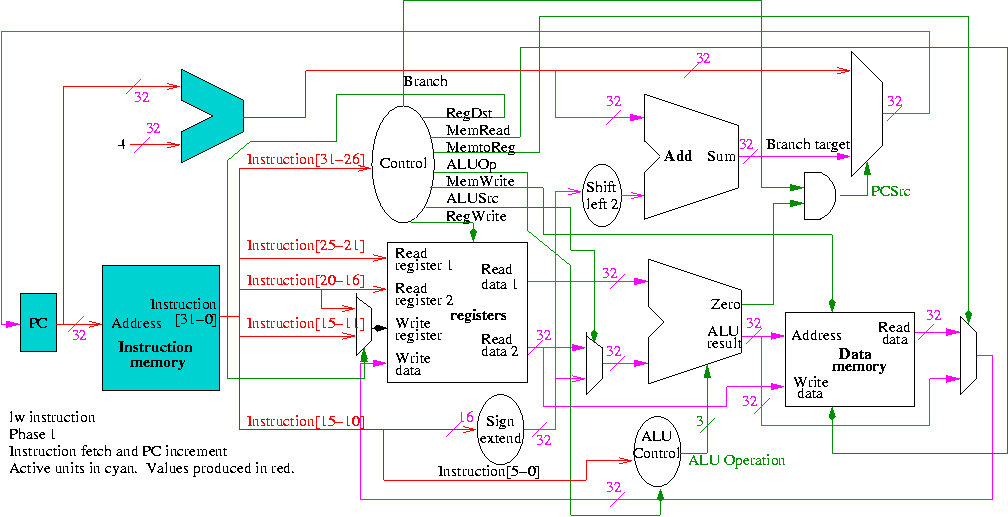
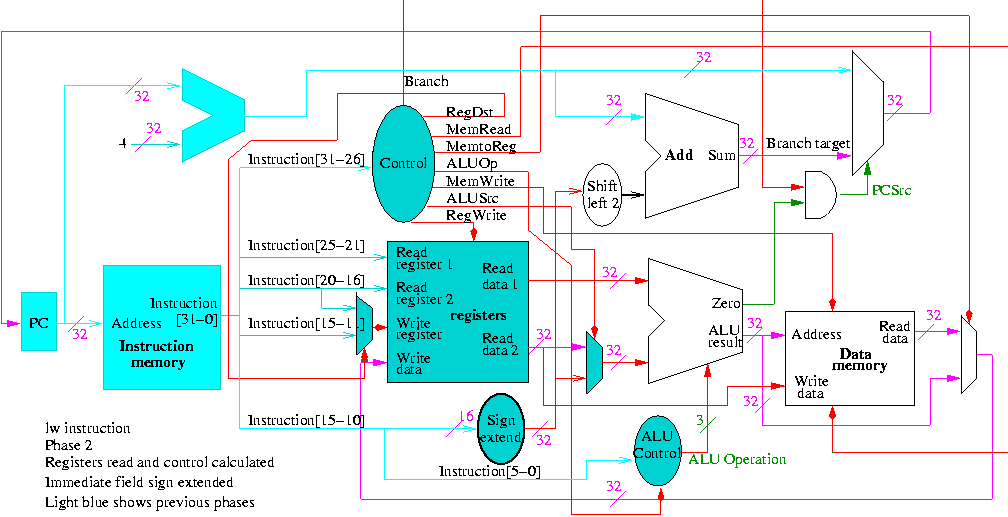
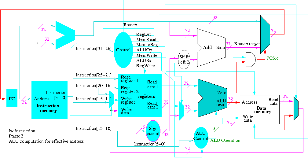
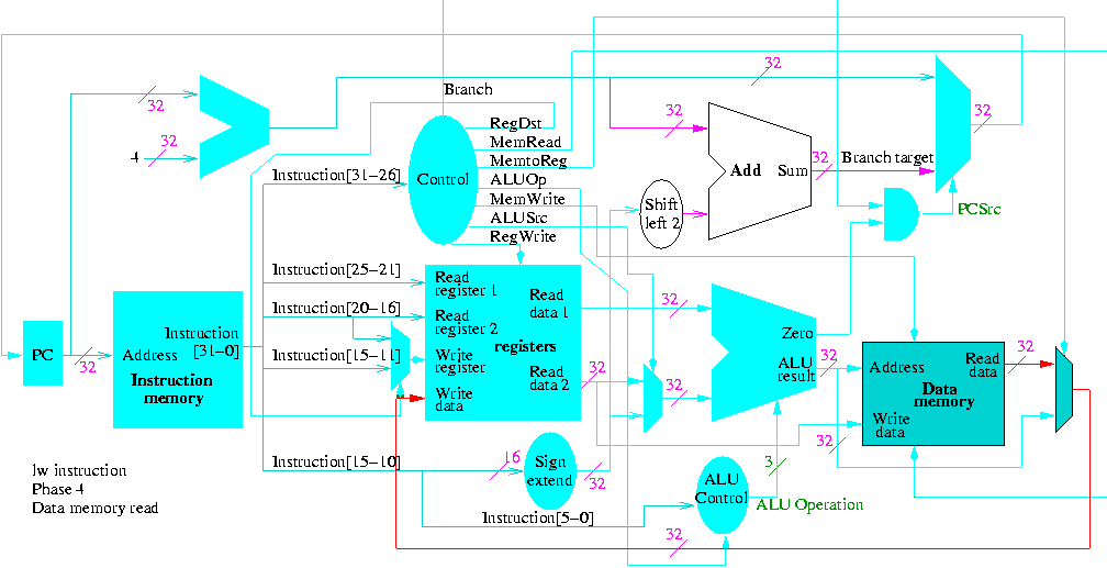
The following truth table shows the settings for the control lines for each opcode. This is drawn differently since the labels of what should be the columns are long (e.g. RegWrite) and it is easier to have long labels for rows.
| Signal | R-type | lw | sw | beq |
|---|---|---|---|---|
| Op5 | 0 | 1 | 1 | 0 |
| Op4 | 0 | 0 | 0 | 0 |
| Op3 | 0 | 0 | 1 | 0 |
| Op2 | 0 | 0 | 0 | 1 |
| Op1 | 0 | 1 | 1 | 0 |
| Op0 | 0 | 1 | 1 | 0 |
| RegDst | 1 | 0 | X | X |
| ALUSrc | 0 | 1 | 1 | 0 |
| MemtoReg | 0 | 1 | X | X |
| RegWrite | 1 | 1 | 0 | 0 |
| MemRead | 0 | 1 | 0 | 0 |
| MemWrite | 0 | 0 | 1 | 0 |
| Branch | 0 | 0 | 0 | 1 |
| ALUOp1 | 1 | 0 | 0 | 0 |
| ALUOp | 0 | 0 | 0 | 1 |
Now it is straightforward but tedious to get the logic equations
When drawn in pla style the circuit is

Homework: 5.5 and 5.8 (control, we already did the datapath), 5.1, 5.2, 5.10 (just the single-cycle datapath) 5.11.