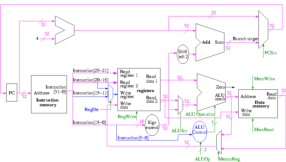
We start with our last figure, which shows the data path and then add the missing mux and show how the instruction is broken down.
We need to set the muxes.
We need to generate the three ALU cntl lines: 1-bit Bnegate and 2-bit OP
    And     0 00
    Or      0 01
    Add     0 10
    Sub     1 10
    Set-LT  1 11
Homework:
What happens if we use 1 00 for the three ALU control lines?
What if we use 1 01?
What information can we use to decide on the muxes and alu cntl lines?
The instruction!
So no problem, just do a truth table.
We will let the main control (to be done later) ``summarize'' the opcode for us. It will generate a 2-bit field ALUOp
    ALUOp   Action needed by ALU

    00      Addition (for load and store)
    01      Subtraction (for beq)
    10      Determined by funct field (R-type instruction)
    11      Not used
How many entries do we have now in the truth table?
| opcode | ALUOp | operation | funct field | ALU action | ALU cntl |
|---|---|---|---|---|---|
| LW | 00 | load word | xxxxxx | add | 010 |
| SW | 00 | store word | xxxxxx | add | 010 |
| BEQ | 01 | branch equal | xxxxxx | subtract | 110 |
| R-type | 10 | add | 100000 | add | 010 |
| R-type | 10 | subtract | 100010 | subtract | 110 |
| R-type | 10 | AND | 100100 | and | 000 |
| R-type | 10 | OR | 100101 | or | 001 |
| R-type | 10 | SLT | 101010 | set on less than | 111 |
    ALUOp | Funct        ||  Bnegate:OP
    1 0   | 5 4 3 2 1 0  ||  B OP
    ------+--------------++------------
    0 0   | x x x x x x  ||  0 10
    x 1   | x x x x x x  ||  1 10
    1 x   | x x 0 0 0 0  ||  0 10
    1 x   | x x 0 0 1 0  ||  1 10
    1 x   | x x 0 1 0 0  ||  0 00
    1 x   | x x 0 1 0 1  ||  0 01
    1 x   | x x 1 0 1 0  ||  1 11
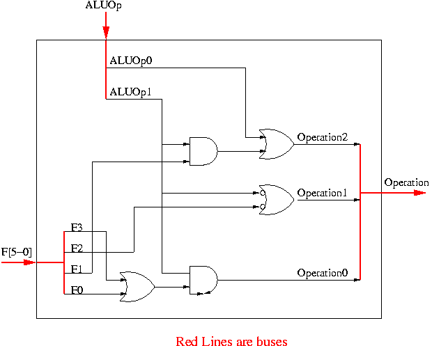
How would we implement this?
ALUOp | Funct
1 0   | 5 4 3 2 1 0
------+------------
x 1   | x x x x x x
1 x   | x x 0 0 1 0
1 x   | x x 1 0 1 0
ALUOp | Funct
1 0   | 5 4 3 2 1 0
------+-------------
x 1   | x x x x x x
1 x   | x x x x 1 x
When is OP0 asserted?
ALUOp | Funct
1 0   | 5 4 3 2 1 0
------+------------
1 x   | x x 0 1 0 1
1 x   | x x 1 0 1 0
ALUOp | Funct
1 0   | 5 4 3 2 1 0
------+------------
1 x   | x x x x x 1
1 x   | x x 1 x x x
ALUOp | Funct
1 0   | 5 4 3 2 1 0
------+------------
0 0   | x x x x x x
x 1   | x x x x x x
1 x   | x x 0 0 0 0
1 x   | x x 0 0 1 0
1 x   | x x 1 0 1 0
ALUOp | Funct
1 0   | 5 4 3 2 1 0
------+------------
0 0   | x x x x x x
x 1   | x x x x x x
1 x   | x x x 0 x x
ALUOp | Funct
1 0   | 5 4 3 2 1 0
------+------------
0 x   | x x x x x x
1 x   | x x x 0 x x
ALUOp | Funct
1 0   | 5 4 3 2 1 0
------+------------
0 x   | x x x x x x
x x   | x x x 0 x x
The circuit is then easy.
Now we need the main control.
So 9 bits.
The following figure shows where these occur.
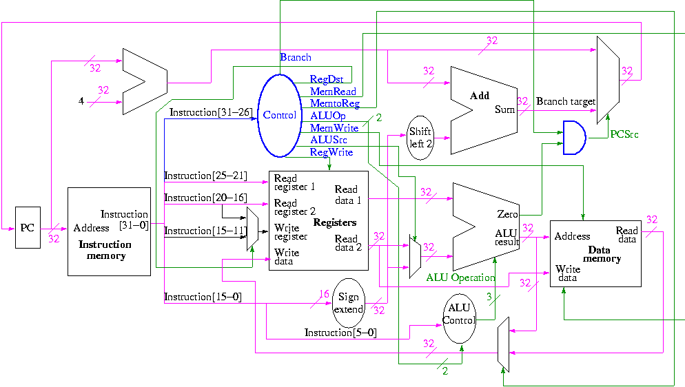
They all are determined by the opcode
The MIPS instruction set is fairly regular. Most fields we need are always in the same place in the instruction.
| MemRead: | Memory delivers the value stored at the specified addr |
| MemWrite: | Memory stores the specified value at the specified addr |
| ALUSrc: | Second ALU operand comes from (reg-file / sign-ext-immediate) |
| RegDst: | Number of reg to write comes from the (rt / rd) field |
| RegWrite: | Reg-file stores the specified value in the specified register |
| PCSrc: | New PC is Old PC+4 / Branch target |
| MemtoReg: | Value written in reg-file comes from (alu / mem) |
We have seen the wiring before.
We are interested in four opcodes.
Do a stage play
add r9,r5,r1 r9=r5+r1   0   5   1   9   0  32
sub r9,r9,r6            0   9   6   9   0  34
beq r9,r0,-8            4   9   0   <  -2   >
slt r1,r9,r0            0   9   0   1   0  42
lw  r1,102(r2)         35   2   1   <  100  >
sw  r9,102(r2)