======== START LECTURE #14
========
Chapter 5: The processor: datapath and control
Homework:
Start Reading Chapter 5.
5.1: Introduction
We are going to build the MIPS processor
Figure 5.1 redrawn below shows the main idea

Note that the instruction gives the three register numbers as well
as an immediate value to be added.
- No instruction actually does all this.
- We have datapaths for all possibilities.
- Will see how we arrange for only certain datapaths to be used for
each instruction type.
- For example R type uses all three registers but not the
immediate field.
- The I type uses the immediate but not all three registers.
- The memory address for a load or store is the sum of a register
and an immediate.
- The data value to be stored comes from a register.
5.2: Building a datapath
Let's begin doing the pieces in more detail.

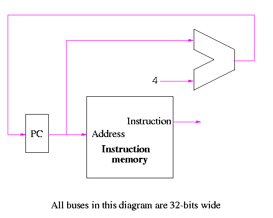
Instruction fetch
We are ignoring branches for now.
- How come no write line for the PC register?
- Ans: We write it every cycle.
- How come no control for the ALU
- Ans: This one always adds

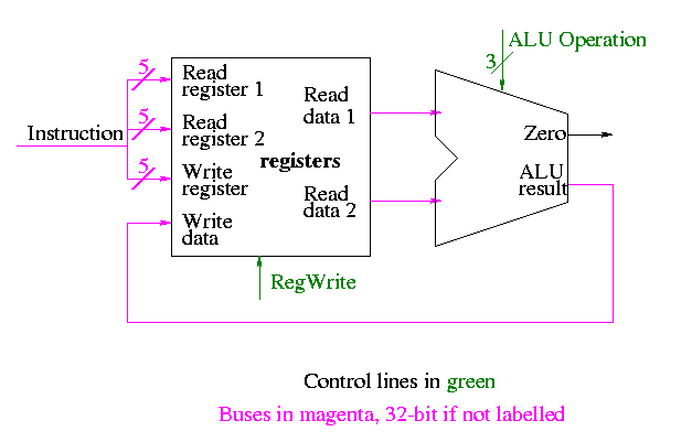
R-type instructions
- ``Read'' and ``Write'' in the diagram are adjectives not verbs.
- The 32-bit bus with the instruction is divided into three 5-bit
buses for each register number (plus other wires not shown).
- Two read ports and one write port, just as we learned in chapter 4.
- The 3-bit control consists of Bnegate and Op from chapter 4.
- The RegWrite control line is always asserted for R-type
instructions.
Homework: What would happen if the RegWrite line
had a stuck-at-0 fault (was always deasserted)?
What would happen if the RegWrite line
had a stuck-at-1 fault (was always asserted)?

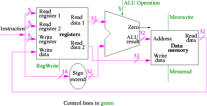
load and store
lw  $r,disp($s)
sw  $r,disp($s)
lw $r,disp($s):
- Computes the effective address formed by adding the 16-bit
immediate constant ``disp'' to the contents of register $s.
- Fetches the value in data memory at this address.
- Inserts this value into register $r.
sw $r,disp($s):
- Computes the same effective address as lw $r,disp($s)
- Stores the contents of register $r into this address
- We have a 32-bit adder so need to extend the 16-bit immediate
constant to 32 bits. Produce an additional 16 HOBs all equal to the
sign bit of the 16-bit immediate constant. This is called sign
extending the constant.
- RegWrite is deasserted for sw and asserted for lw.
- MemWrite is asserted for sw and deasserted for lw.
- I don't see the need for MemRead; perhaps it is there for power
saving.
- The ALU Operation is set to add for lw and sw.
- For now we just write down which control lines are asserted and
deasserted. Later we will do the circuit for to calculate the control
lines from the instruction word.
Homework: What would happen if the RegWrite line
had a stuck-at-0 fault (was always deasserted)?
What would happen if the RegWrite line
had a stuck-at-1 fault (was always asserted)?
What would happen if the MemWrite line
had a stuck-at-0 fault (was always deasserted)?
What would happen if the MemWrite line
had a stuck-at-1 fault (was always asserted)?
There is a cheat here.
- For lw we read register r (and read s)
- For sw we write register r (and read s)
- But we indicated that the same bits in the instruction always go to
the same ports in the register file.
- We are ``mux deficient''.
- We will put in the mux later


