======== START LECTURE #6
========
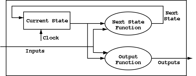
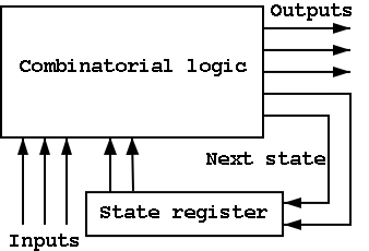
B.6: Finite State Machines (FSMs)
I do a different example from the book (counters instead of traffic
lights). The ideas are the same and the two generic pictures (below)
apply to both examples.
Counters
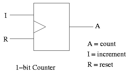
A counter counts (naturally).
- The counting is done in binary.
- Increments (i.e., counts) on clock ticks (active edge).
- Actually only on those clocks ticks when the ``increment'' line is
asserted.
- If reset asserted at a clock tick, the counter is reset to zero.
- What if both reset and increment assert?
Ans: Shouldn't do that. Will accept any answer (i.e., don't care).
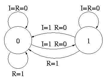
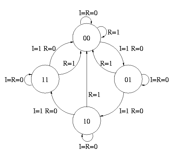
The state transition diagram
- The figure shows the state transition diagram for A, the output of
a 1-bit counter.
- In this implementation, if R=I=1 we choose to set A to zero. That
is, if Reset and Increment are both asserted, we do the Reset.
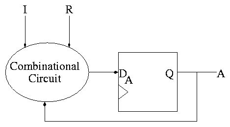
The circuit diagram.
- Uses one flop and a combinatorial circuit.
- The (combinatorial) circuit is determined by the transition diagram.
- The circuit must calculate the next value of A from the current
value and I and R.
- The flop producing A is often itself called A and the D input to this
flop is called DA.
- To fit the diagram above for FSMs, we should not draw the overall
output (A) coming from the flop (state register) but instead from the
combinational circuit (which is easy since A is input to that circuit).
How do we determine the combinatorial circuit?
- This circuit has three inputs, I, R, and the current A.
- It has one output, DA, which is the desired next A.
- So we draw a truth table, as before.
- For convenience I added the label Next A to the DA column
Current      || Next A
   A    I R  || DA <-- i.e. to what must I set DA
-------------++--      in order to get the desired
   0    0 0  || 0      Next A for the next cycle.
   1    0 0  || 1
   0    1 0  || 1
   1    1 0  || 0
   x    x 1  || 0
But this table is simply the truth table for the combinatorial
circuit.
A I R  || DA
-------++--
0 0 0  || 0
1 0 0  || 1
0 1 0  || 1
1 1 0  || 0
x x 1  || 0

DA = R' (A XOR I)
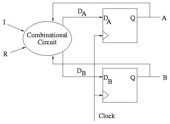
How about a two bit counter.
- State diagram has 4 states 00, 01, 10, 11 and transitions from one
to another.
- The circuit diagram has 2 D-flops.
To determine the combinatorial circuit we could precede as before
Current      ||
  A B   I R  || DA DB
-------------++------
This would work but we can instead think about how a counter works and
see that.
DA = R'(A XOR I)
DB = R'(B XOR AI)
Homework: B.23
B.7 Timing Methodologies
Skipped
Simulating Combinatorial Circuits at the Gate Level
The idea is, given a circuit diagram, write a program that behaves the
way the circuit does. This means more than getting the same answer.
The program is to work the way the circuit does.
For each logic box, you write a procedure with the following properties.
- A parameters is defined for each input and output wire.
- A (local) variable is defined for each internal wire.
Really means a variable define for each signal. If a signal is
sent from one gate to say 3 others, you might not call all those
connections one wire, but it is one signal and is represented by
one variable
- The only operations used are AND OR XOR NOT
- In C or Java & | ^ !
- Other languages similar.
- Java is particularly well suited since it has variables and
constants of type Boolean.
- An assignment statement (with an operator) corresponds to a
gate.
For example A = B & C; would mean that there is an AND gate with
input wires B and C and output wire A.
- NO conditional assignment.
- NO if then else statements.
We know how to implement a mux using ANDs, ORs, and NOTs.
- Single assignment to each variable.
Multiple assignments would correspond to a cycle or to two outputs
connected to the same wire.
- A bus (i.e., a set of signals) is represented by an array.
- Testing
- Exhaustive possible for 1-bit cases.
- Cleverness for n-bit cases (n=32, say).
Simulating a Full Adder
Remember that a full adder has three inputs and two outputs.
Discuss FullAdder.c or perhaps
FullAdder.java.
Simulating a 4-bit Adder
This implementation uses the full adder code above.
Discuss FourBitAdder.c or perhaps
FourBitAdder.java