The first way we solved part E shows that any logic function can be written using just AND, OR, and NOT.
DeMorgan's laws:
You prove DM laws with TTs. Indeed that is ...
Homework: B.6 on page B-45.
Do beginning of HW on the board.
With DM (DeMorgan's Laws) we can do quite a bit without resorting to TTs. For example one can show that the two expressions for E in the example above (page B-6) are equal. Indeed that is
Homework: B.7 on page B-45
Do beginning of HW on board.
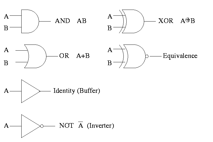
Gates implement the basic logic functions: AND OR NOT XOR Equivalence

We often omit the inverters and draw the little circles at the input or output of the other gates (AND OR). These little circles are sometimes called bubbles.
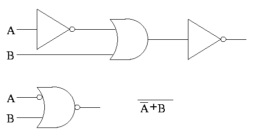
This explains why the inverter is drawn as a buffer with a bubble.
Show why the picture for equivalence is the negation of XOR, i.e (A XOR B)' is AB + A'B'
(A XOR B)' =
(A'B+AB')' =
(A'B)' (AB')' =
(A''+B') (A'+B'') =
(A + B') (A' + B) =
AA' + AB + B'A' + B'B =
0   + AB + B'A' + 0 =
AB + A'B'
Homework: B.2 on page B-45 (I previously did the first part of this homework).
Homework: Consider the Boolean function of 3 boolean vars (i.e. a three input function) that is true if and only if exactly 1 of the three variables is true. Draw the TT. Draw the logic diagram with AND OR NOT. Draw the logic diagram with AND OR and bubbles.
A set of gates is called universal if these gates are sufficient to generate all logic functions.
NOR (NOT OR) is true when OR is false. Do TT.
NAND (NOT AND) is true when AND is false. Do TT.
Draw two logic diagrams for each, one from the definition and an equivalent one with bubbles.
Theorem A 2-input NOR is universal and a 2-input NAND is universal.
Proof
We must show that you can get A', A+B, and AB using just a two input NOR.
Homework: Show that a 2-input NAND is universal.
Can draw NAND and NOR each two ways (because (AB)' = A' + B')
We have seen how to get a logic function from a TT. Indeed we can get one that is just two levels of logic. But it might not be the simplest possible. That is, we may have more gates than are necessary.
Trying to minimize the number of gates is NOT trivial. Mano covers the topic of gate minimization in detail. We will not cover it in this course. It is not in H&P. I actually like it but must admit that it takes a few lectures to cover well and it not used much in practice since it is algorithmic and is done automatically by CAD tools.
Minimization is not unique, i.e. there can be two or more minimal forms.
Given A'BC + ABC + ABC'
Combine first two to get BC + ABC'
Combine last two to get A'BC + AB
Sometimes when building a circuit, you don't care what the output is for certain input values. For example, that input combination might be known not to occur. Another example occurs when, for some combination of input values, a later part of the circuit will ignore the output of this part. These are called don't care outputs. Making use of don't cares can reduce the number of gates needed.
Can also have don't care inputs when, for certain values of a subset of the inputs, the output is already determined and you don't have to look at the remaining inputs. We will see a case of this in the very next topic, multiplexors.
Putting a circuit in disjunctive normal form (i.e. two levels of logic) means that every path from the input to the output goes through very few gates. In fact only two, an OR and an AND. Maybe we should say three since the AND can have a NOT (bubble). Theorticians call this number (2 or 3 in our case) the depth of the circuit. Se we see that every logic function can be implemented with small depth. But what about the width, i.e., the number of gates.
The news is bad. The parity function takes n inputs and gives TRUE if and only if the number of TRUE inputs is odd. If the depth is fixed (say limited to 3), the number of gates needed for parity is exponential in n.
Homework: Read B.3.
Generic Homework: Read sections in book corresponding to the lectures.
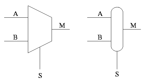
Often called a mux or a selector
Show equivalent circuit with AND OR
Hardware if-then-else
    if S=0
        M=A
    else
        M=B
    endif
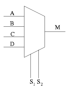
This is an if-then-elif-elif-else
   if S1=0 and S2=0
        M=A
    elif S1=0 and S2=1
        M=B
    elif S1=1 and S2=0
        M=C
    else -- S1=1 and S2=1
        M=D
    endif
Do a TT for 2 way mux. Redo it with don't care values.
Do a TT for 4 way mux with don't care values.
Homework:
B.12.
B.5 (Assume you have constant signals 1 and 0 as well.)
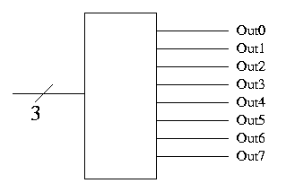
Basically, the opposite of a mux.