Computer Systems Design
Chapter 4
Homework:
Read 4.1-4.4
4.2: Signed and Unsigned Numbers
MIPS uses 2s complement (just like 8086)
To form the 2s complement (of 0000 1111 0000 1010 0000 0000 1111 1100)
- Take the 1s complement.
- That is, complement each bit (1111 0000 1111 0101 1111 1111 0000 0011)
- Then add 1 (1111 0000 1111 0101 1111 1111 0000 0100)
Need comparisons for signed and unsigned.
- For signed a leading 1 is smaller (negative) than a leading 0
- For unsigned a leading 1 is larger than a leading 0
sltu and sltiu
Like slt and slti but the comparison is unsigned.
Homework:
4.1-4.9
4.3: Addition and subtraction
To add two (signed) numbers just add them. That is don't treat
the sign bit special.
To subtract A-B, just take the 2s complement of B and add.
Overflows
An overflow occurs when the result of an operation cannot be
represented with the available hardware. For MIPS this means when the
result does not fit in a 32-bit word.
- We have 31 bits plus a sign bit.
- The result would definitely fit in 33 bits (32 plus sign)
- The hardware simply discards the carry out of the top (sign) bit
- This is not wrong--consider -1 + -1
  11111111111111111111111111111111   (32 ones is -1)
+ 11111111111111111111111111111111
----------------------------------
 111111111111111111111111111111110   Now discard the carry out

  11111111111111111111111111111110   this is -2
- The bottom 31 bits are always correct.
Overflow occurs when the 32 (sign) bit is set to a value and not
the sign.
- Here are the conditions for overflow
Operation  Operand A  Operand B  Result
   A+B       >= 0        >= 0      < 0
   A+B        < 0         < 0     >= 0
   A-B       >= 0         < 0      < 0
   A-B        < 0        >= 0     >= 0
- These conditions are the same as
Carry-In to sign position != Carry-Out
Homework:
Prove this last statement (4.29)
(for fun only, do not hand in).
addu, subu, addiu
These three instructions perform addition and subtraction the same way
as do add and sub, but do not signal overflow
4.4: Logical Operations
Shifts: sll, srl
- R type, with shamt used and rs not used.
- sll $10,$20,5
reg10 gets reg20 shifted left 5 bits.
- Why do we need both sll and srl,
i.e, why not just have one of them and use a negative
shift amt for the other?
Ans: The shift amt is only 5 bits and need shifts from 0 to 31
bits. Hence not enough bits for negative shifts.
- These are shifts not rotates.
- Op is 0 (these are ALU ops, will understand why in a few weeks).
Bitwise AND and OR: and, or, andi, ori
No surprises.
- and $r1,$r2,$r3
or $r1,$r2,$r3
- standard R-type instruction
- andi $r1,$r2,100
ori $r1,$r2,100
- standard I-type
4.5: Constructing an ALU--the fun begins
First goal is 32-bit AND, OR, and addition
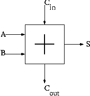
Recall we know how to build a full adder. We will draw it as shown on
the right.
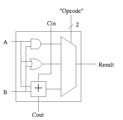
With this adder, the ALU is easy.
- Just choose the correct operation (ADD, AND, OR)
- Note the principle that if you want a logic box that sometimes
computes X and sometimes computes Y, what you do is
- Always compute X.
- Always compute Y.
- Put both X and Y into a mux.
- Use the ``sometimes'' condition as the select line to the mux.
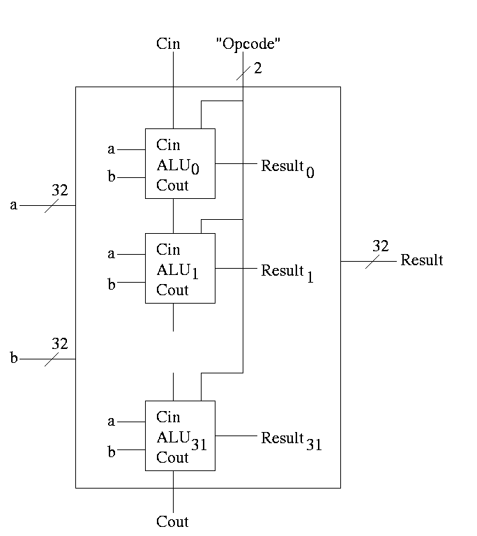
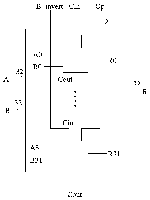
With this 1-bit ALU, constructing a 32-bit version is simple.
- Use an array of logic elements for the logic. The logic element
is the 1-bit ALU
- Use buses for A, B, and Result.
- ``Broadcast'' Opcode to all of the internal 1-bit ALUs. This
means wire the external Opcode to the Opcode input of each of the
internal 1-bit ALUs
First goal accomplished.
======== START LECTURE #9
========
Implementing Addition and Subtraction
We wish to augment the ALU so that we can perform subtraction
(as well as addition, AND, and OR).
- Big deal about 2's compliment is that
A - B = A + (2's comp B)
= A + (B' + 1).
- Get B' from an inverter (naturally).
- Get +1 from the Carry-In (clever).
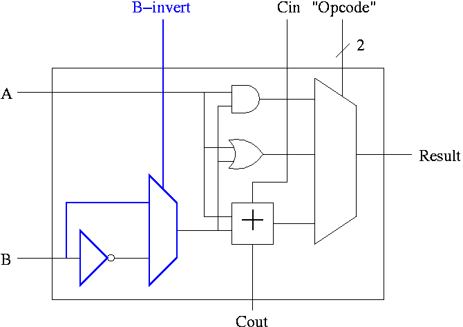
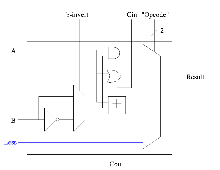
A 1-bit ALU with ADD, SUB, AND, OR is shown on the right.
- To implement addition we use opcode 10 as before and de-assert
both b-invert and Cin.
- To implement subtraction we still use opcode 10 but we assert
both b-invert and Cin.
32-bit version is simply a bunch of these.
- For subtraction assert both B-invert and Cin.
- For addition de-assert both B-invert and Cin.
- For AND and OR de-assert B-invert. Cin is a don't care.
- We could get for A+B' (by asserting b-invert and
de-asserting Cin)
If we then let A=0, this gives B', i.e. the NOT operation
However, we will not use it. Indeed we will soon give it away.
(More or less) all ALUs do AND, OR, ADD, SUB.
Now we want to customize our ALU for the MIPS architecture,
which has a few extra requirements.
- slt set-less-than
- Overflows
- Zero Detect
Implementing SLT
This is fairly clever as we shall see.
- Result reg is 1 if a < b
Result reg is 0 if a >= b
- So need to set the LOB (low order bit, aka least significant bit)
of the result equal to the sign bit of a subtraction, and set the
rest of the result bits to zero.
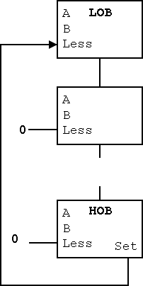
- Idea #1. Give the mux another input, called LESS.
This input is brought in from outside the bit cell.
That is, if the opcode is slt we make the select line to the
mux equal to 11 (three) so that the the output is the this new
input. For all the bits except the LOB, the LESS input is
zero. For the LOB we must figure out how to set LESS.
-
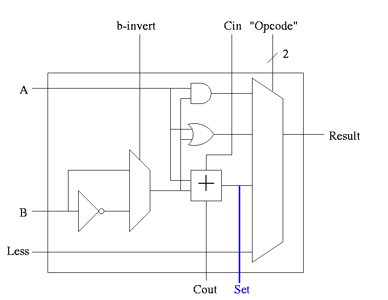
Idea #2. Bring out the result of the adder (BEFORE the mux)
Only needed for the HOB (high order bit, i.e. sign) Take this
new output from the HOB, call it SET and connect it to the
LESS input in idea #1 for the LOB. The LESS input for other
bits are set to zero.
- Why isn't this method used?
- Ans: It is wrong!
- Example using 3 bit numbers (i.e. -4 .. 3).
- Try slt on -3 and +2.
- True subtraction (-3 - +2) gives -5.
- The negative sign in -5 indicates (correctly) that -3 < +2.
- But three bit subtraction -3 - +2 gives +3 !
- Hence we will incorrectly conclude that -3 is NOT less than +2.
- (Really, the subtraction signals an overflow.
unless doing unsigned)
-
Solution: Need the correct rule for less than (not just sign of
subtraction).
Homework: figure out correct rule, i.e. prob 4.23.
Hint: when an overflow occurs the sign bit is definitely wrong (so the
complement of the sign bit is right).
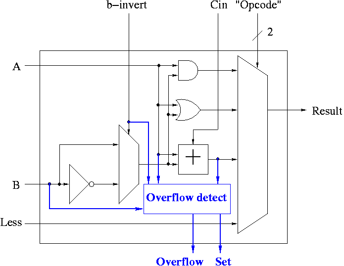
Implementing Overflow Detection
- The HOB ALU is already unique (outputs SET).
- Need to enhance it some more to produce the overflow output.
- Recall that we gave the rule for overflow. You need to examine:
- Whether the operation is add or sub (binvert).
- The sign of A.
- The sign of B.
- The sign of the result.
- Since this is the HOB we have all the sign bits.
- The book also uses Cout, but this appears to be an error.
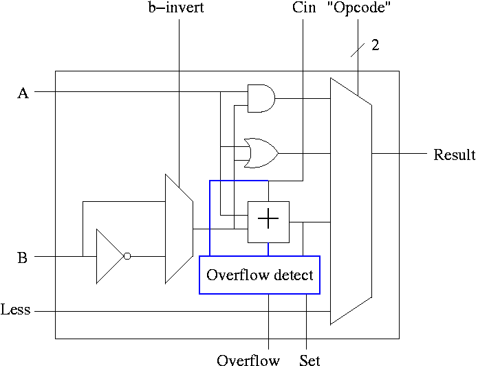
Simpler Overflow Detection
Recall the simpler overflow detection: An overflow occurs if and
only if the carry in to the HOB differs from the carry out of the HOB.
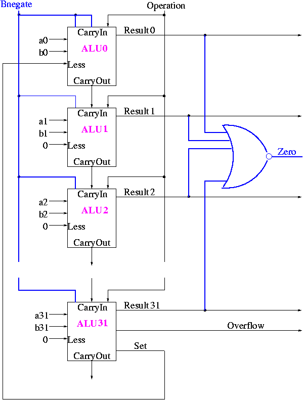
Implementing Zero Detection
- To see if all bits are zero just need the NOR of all the bits
- Conceptually trivially but does require some wiring
Observation: The CarryIn to the LOB and Binvert
to all the 1-bit ALUs are always the same.
So the 32-bit ALU has just one input called Bnegate, which is sent
to the appropriate inputs in the 1-bit ALUs.
The Final Result is
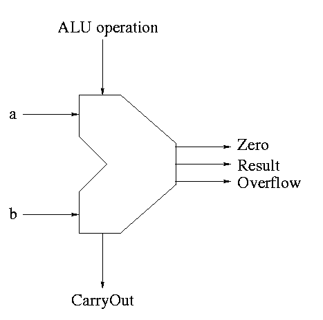
The symbol used for an ALU is on the right
What are the control lines?
-
Bnegate (1 bit)
-
OP (2 bits)
What functions can we perform?
-
and
-
or
-
add
-
sub
-
set on less than
What (3-bit) values for the control lines do we need for each
function? The control lines are Bnegate (1-bit) and Operation (2-bits)
| and | 0 | 00 |
| or | 0 | 01 |
| add | 0 | 10 |
| sub | 1 | 10 |
| slt | 1 | 11 |
======== START LECTURE #10
========
Fast Adders
-
We have done what is called a ripple carry adder.
- The carry ``ripples'' from one bit to the next (LOB to HOB).
- So the time required is proportional to the wordlength
- Each carry can be computed with two levels of logic (any function
can be so computed) hence the number of gate delays for an n bit
adder is 2n.
- For a 4-bit adder 8 gate delays are required.
- For an 16-bit adder 32 gate delays are required.
- For an 32-bit adder 64 gate delays are required.
- For an 64-bit adder 128 gate delays are required.
-
What about doing the entire 32 (or 64) bit adder with 2 levels of
logic?
-
Such a circuit clearly exists. Why?
Ans: A two levels of logic circuit exists for any
function.
-
But it would be very expensive: many gates and wires.
-
The big problem: When expressed with two levels of
login, the AND and OR gates have high
fan-in, i.e., they have a large number of inputs. It is
not true that a 64-input AND takes the same time as a
2-input AND.
-
Unless you are doing full custom VLSI, you get a toolbox of
primative functions (say 4 input NAND) and must build from that
-
There are faster adders, e.g. carry lookahead and carry save. We
will study carry lookahead adders.
Carry Lookahead Adder (CLA)
This adder is much faster than the ripple adder we did before,
especially for wide (i.e., many bit) addition.
- For each bit position we have two input bits, a and b (really
should say ai and bi as I will do below).
- We can, in one gate delay, calculate two other bits
called generate g and propagate p, defined as follows:
- The idea for propagate is that p is true if the
current bit will propagate a carry from its input to its output.
- It is easy to see that p = (a OR b), i.e.
if and only if (a OR b)
then if there is a carry in
then there is a carry out
- The idea for generate is that g is true if the
current bit will generate a carry out (independent of the carry in).
- It is easy to see that g = (a AND b), i.e.
if and only if (a AND b)
then the must be a carry-out independent of the carry-in
To summarize, using a subscript i to represent the bit number,
    to generate  a carry:   gi = ai bi
    to propagate a carry:   pi = ai+bi
H&P give a plumbing analogue
for generate and propagate.
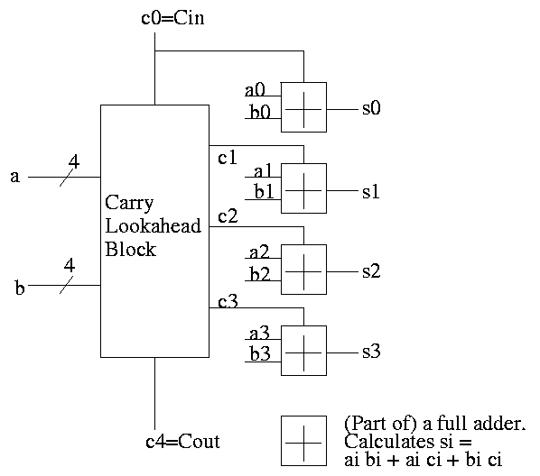
Given the generates and propagates, we can calculate all the carries
for a 4-bit addition (recall that c0=Cin is an input) as follows (this
is the formula version of the plumbing):
c1 = g0 + p0 c0

c2 = g1 + p1 c1 = g1 + p1 g0 + p1 p0 c0

c3 = g2 + p2 c2 = g2 + p2 g1 + p2 p1 g0 + p2 p1 p0 c0

c4 = g3 + p3 c3 = g3 + p3 g2 + p3 p2 g1 + p3 p2 p1 g0 + p3 p2 p1 p0 c0
Thus we can calculate c1 ... c4 in just two additional gate delays
(where we assume one gate can accept upto 5 inputs). Since we get gi
and pi after one gate delay, the total delay for calculating all the
carries is 3 (this includes c4=Carry-Out)
Each bit of the sum si can be calculated in 2 gate delays given ai,
bi, and ci. Thus, for 4-bit addition, 5 gate delays after we are
given a, b and Carry-In, we have calculated s and Carry-Out.
So, for 4-bit addition, the faster adder takes time 5 and the slower
adder time 8.
Now we want to put four of these together to get a fast 16-bit
adder.
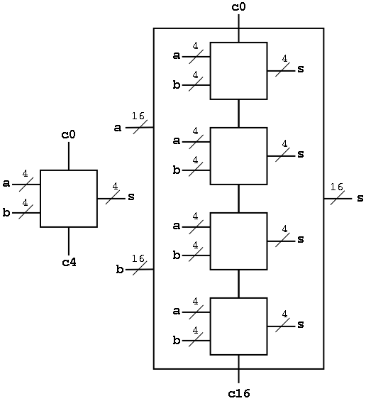
As black boxes, both ripple-carry adders and carry-lookahead adders
(CLAs) look the same.
We could simply put four CLAs together and let the Carry-Out from
one be the Carry-In of the next. That is, we could put these CLAs
together in a ripple-carry manner to get a hybrid 16-bit adder.
- Since the Carry-Out is calculated in 3 gate delays, the Carry-In to
the high order 4-bit adder is calculated in 3*3=9 delays.
- Hence the overall Carry-Out takes time 9+3=12 and the high order
four bits of the sum take 9+5=14. The other bits take less time.
- So this mixed 16-bit adder takes 14 gate delays compared with
2*16=32 for a straight ripple-carry 16-bit adder.
We want to do better so we will put the 4-bit carry-lookahead
adders together in a carry-lookahead manner. Thus the diagram above
is not what we are going to do.
- We have 33 inputs a0,...,a15; b0,...b15; c0=Carry-In
- We want 17 outputs s0,...,s15; c16=c=Carry-Out
- Again we are assuming a gate can accept upto 5 inputs.
- It is important that the number of inputs per gate does not grow
with the number of bits in each number.
- If the technology available supplies only 4-input gates (instead
of the 5-input gates we are assuming),
we would use groups of three bits rather than four
We start by determining ``super generate'' and ``super propagate''
bits.
- The super generate indicates whether the 4-bit
adder constructed above generates a Carry-Out.
- The super propagate indicates whether the 4-bit
adder constructed above propagates a
Carry-In to a Carry-Out.
P0 = p3 p2 p1 p0          Does the low order 4-bit adder
                          propagate a carry?
P1 = p7 p6 p5 p4

P2 = p11 p10 p9 p8

P3 = p15 p14 p13 p12      Does the high order 4-bit adder
                          propagate a carry?


G0 = g3 + p3 g2 + p3 p2 g1 + p3 p2 p1 g0        Does low order 4-bit
                                                adder generate a carry
G1 = g7 + p7 g6 + p7 p6 g5 + p7 p6 p5 g4

G2 = g11 + p11 g10 + p11 p10 g9 + p11 p10 p9 g8

G3 = g15 + p15 g14 + p15 p14 g13 + p15 p14 p13 g12

From these super generates and super propagates, we can calculate the
super carries, i.e. the carries for the four 4-bit adders.
- The first super carry
C0, the Carry-In to the low-order 4-bit adder, is just c0 the input
Carry-In.
- The second super carry C1 is the Carry-Out of the low-order 4-bit
adder (which is also the Carry-In to the 2nd 4-bit adder.
- The last super carry C4 is the Carry-out of the high-order 4-bit
adder (which is also the overall Carry-out of the entire 16-bit adder).
C1 = G0 + P0 c0

C2 = G1 + P1 C1 = G1 + P1 G0 + P1 P0 c0

C3 = G2 + P2 C2 = G2 + P2 G1 + P2 P1 G0 + P2 P1 P0 c0

C4 = G3 + P3 C3 = G3 + P3 G2 + P3 P2 G1 + P3 P2 P1 G0 + P3 P2 P1 P0 c0
Now these C's (together with the original inputs a and b) are just
what the 4-bit CLAs need.
How long does this take, again assuming 5 input gates?
- We calculate the p's and g's (lower case) in 1 gate delay (as with
the 4-bit CLA).
- We calculate the P's one gate delay after we have the p's or
2 gate delays after we start.
- The G's are determined 2 gate delays after we have the g's and
p's. So the G's are done 3 gate delays after we start.
- The C's are determined 2 gate delays after the P's and G's. So
the C's are done 5 gate delays after we start.
- Now the C's are sent back to the 4-bit CLAs, which have already
calculated the p's and g's. The C's are calculated in 2 more
gate delays (7 total) and the s's 2 more after that (9 total).
In summary, a 16-bit CLA takes 9 cycles instead of 32 for a ripple carry
adder and 14 for the mixed adder.
Some pictures follow.
Take our original picture of the 4-bit CLA and collapse
the details so it looks like.
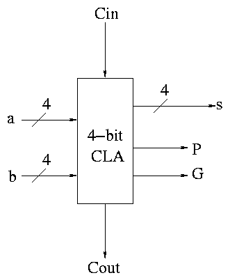
Next include the logic to calculate P and G.
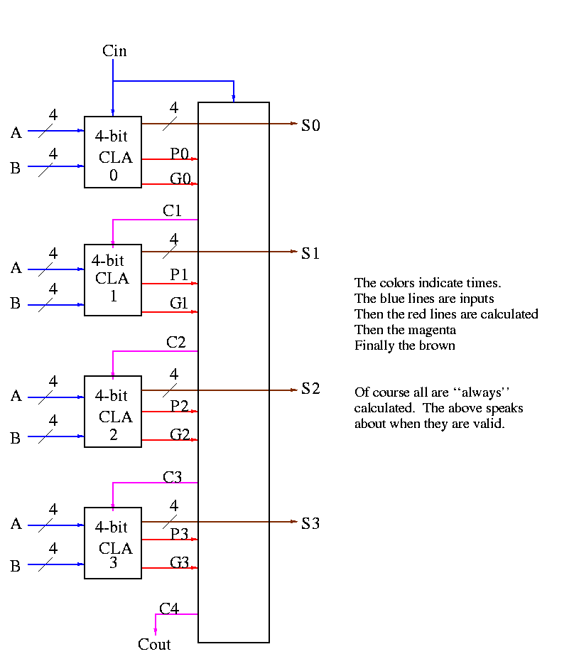
Now put four of these with a CLA block (to calculate C's from P's,
G's and Cin) and we get a 16-bit CLA. Note that we do not
use the Cout from the 4-bit CLAs.
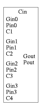
Note that the tall skinny box is general. It takes 4 Ps 4Gs and
Cin and calculates 4Cs. The Ps can be propagates, superpropagates,
superduperpropagates, etc. That is, you take 4 of these 16-bit CLAs
and the same tall skinny box and you get a 64-bit CLA.
Homework:
44, 45
======== START LECTURE #11
========
As noted just above the tall skinny box is useful for all size
CLAs. To expand on that point and to review CLAs, let's redo CLAs with
the general box.
Since we are doing 4-bits at a time, the box takes 9=2*4+1 input bits
and produces 6=4+2 outputs
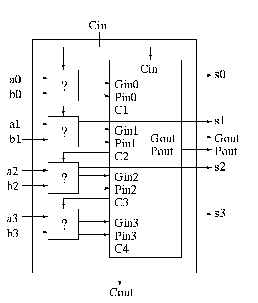
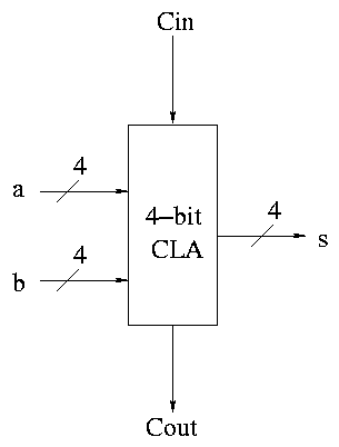
A 4-bit adder is now the figure on the right
What does the ``?'' box do?
- Calculates Gi and Pi based on ai
and bi
- Calculates si based on ai, bi,
and Ci=Cin
- This is part of a normal 1-bit full adder.
- si = ai bi Ci +
ai bi' Ci' +
ai' bi Ci' +
ai' bi' Ci
- Does not bother calculating Cout.
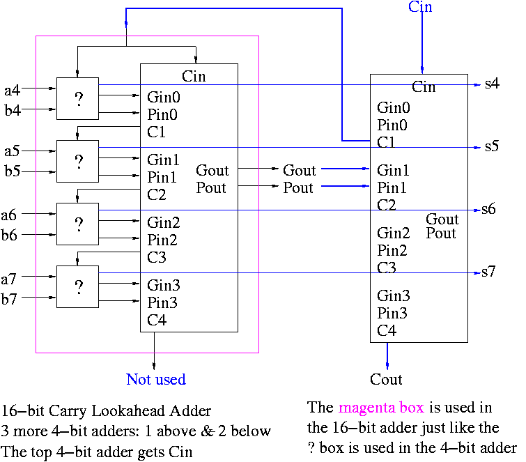
Now take four of these 4-bit adders and use the
identical CLA box to get a 16-bit
adder.
The picture on the right shows ONE 4-bit adder (the magenta box)
used with the CLA box. To get a 16-bit adder you need 3 more magenta
box, one above the one shown (to process bits 0-3) and two below (to
process bits 8-15).
Four of these 16-bit adders with the identical
CLA box gives a 64-bit adder (no picture shown).
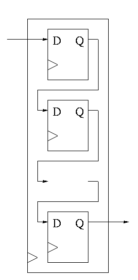
Shifter
This is a sequential circuit.
-
Just a string of D-flops; output of one is input of next
-
Input to first is the serial input.
-
Output of last is the serial output.
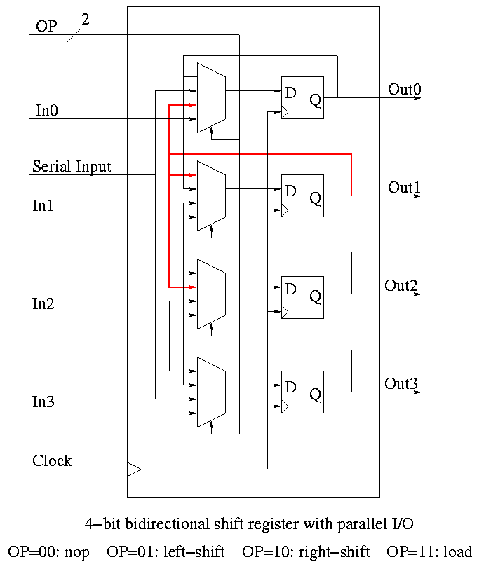
-
We want more.
-
Left and right shifting (with serial input/output).
-
Parallel load.
-
Parallel Output.
-
Don't shift every cycle.
-
Parallel output is just wires.
-
Shifter has 4 modes (left-shift, right-shift, nop, load) so
-
4-1 mux inside.
-
2 select lines are needed.
-
We could modify our registers to be shifters (bigger mux), but ...
-
Our shifters are slow for big shifts; ``barrel shifters'' are
better and kept separate from the processor registers.
Homework:
A 4-bit shift register initially contains 1101. It is
shifted six times to the right with the serial input being
101101. What is the contents of the register after each
shift.
Homework:
Same register, same initial condition. For
the first 6 cycles the opcodes are left, left, right, nop,
left, right and the serial input is 101101. The next cycle
the register is loaded (in parallel) with 1011. The final
6 cycles are the same as the first 6. What is the contents
of the register after each cycle?
4.6: Multiplication
- Of course we can do this with two levels of logic since
multiplication is just a function of its inputs.
- But just as with addition, would have a very big circuit and large
fan in. Instead we use a sequential circuit that mimics the
algorithm we all learned in grade school.
-
Recall how to do multiplication.
-
Multiplicand times multiplier gives product
-
Multiply multiplicand by each digit of multiplier
-
Put the result in the correct column
-
Then add the partial products just produced
-
We will do it the same way ...
... but differently
-
We are doing binary arithmetic so each ``digit'' of the
multiplier is 1 or zero.
-
Hence ``multiplying'' the mulitplicand by a digit of the
multiplier means either
-
Getting the multiplicand
-
Getting zero
-
Use an ``if appropriate bit of multiplier is 1'' stmt
-
To get the ``appropriate bit''
-
Start with the LOB of the multiplier
-
Shift the multiplier right (so the next bit is the LOB)
-
Putting in the correct column means putting it one column
further left than the last time.
-
This is done by shifting the
multiplicand left one bit each time (even if the multiplier
bit is zero).
-
Instead of adding partial products at end, we keep a running sum.
-
If the multiplier bit is zero, add the (shifted)
multiplicand to the running sum
-
If the bit is zero, simply skip the addition.
-
This results in the following algorithm
    product <- 0
    for i = 0 to 31
        if LOB of multiplier = 1
            product = product + multiplicand
        shift multiplicand left 1 bit
        shift multiplier right 1 bit
Do on the board 4-bit multiplication (8-bit registers) 1100 x 1101.
Since the result has (up to) 8 bits, this is often called a 4x4->8
multiply.
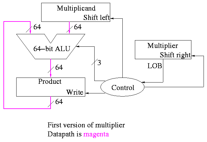
The diagrams below are for a 32x32-->64 multiplier.
What about the control?
-
Always give the ALU the ADD operation
-
Always send a 1 to the multiplicand to shift left
-
Always send a 1 to the multiplier to shift right
-
Pretty boring so far but
-
Send a 1 to write line in product if and only if
LOB multiplier is a 1
-
I.e. send LOB to write line
-
I.e. it really is pretty boring
======== START LECTURE #12
========
This works!
But, when compared to the better solutions to come, is wasteful of
resourses and hence is
-
slower
-
hotter
-
bigger
-
all these are bad
The product register must be 64 bits since the product can contain 64
bits.
Why is multiplicand register 64 bits?
-
So that we can shift it left
-
I.e., for our convenience.
By this I mean it is not required by the problem specification,
but only by the solution method chosen.
Why is ALU 64-bits?
-
Because the product is 64 bits
-
But we are only adding a 32-bit quantity to the
product at any one step.
-
Hmmm.
-
Maybe we can just pull out the correct bits from the product.
-
Would be tricky to pull out bits in the middle
because which bits to pull changes each step
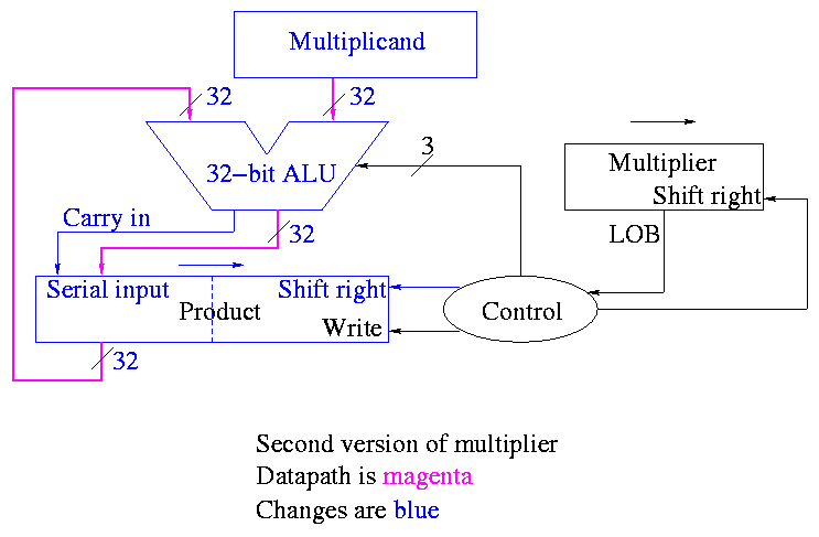
POOF!! ... as the smoke clears we see an idea.
We can solve both problems at once
-
DON'T shift the multiplicand left
-
Hence register is 32-bits.
-
Also register need not be a shifter
-
Instead shift the product right!
-
Add the high-order (HO) 32-bits of product register to the
multiplicand and place the result back into HO 32-bits
-
Only do this if the current multiplier bit is one.
-
Use the Carry Out of the sum as the new bit to shift
in
-
The book forgot the last point but their example used numbers
too small to generate a carry
This results in the following algorithm
    product <- 0
    for i = 0 to 31
        if LOB of multiplier = 1
            (serial_in, product[32-63]) <- product[32-63] + multiplicand
        shift product right 1 bit
        shift multiplier right 1 bit
What about control
-
Just as boring as before
-
Send (ADD, 1, 1) to (ALU, multiplier (shift right), Product
(shift right)).
-
Send LOB to Product (write).
Redo same example on board
A final trick (``gate bumming'', like ``code bumming'' of 60s).
-
There is a waste of registers, i.e. not full unilization.
-
The multiplicand is fully unilized since we always need all 32 bits.
-
But once we use a multiplier bit, we can toss it so we need
less and less of the multiplier as we go along.
-
And the product is half unused at beginning and only slowly ...
-
POOF!!
-
``Timeshare'' the LO half of the ``product register''.
-
In the beginning LO half contains the multiplier.
-
Each step we shift right and more goes to product
less to multiplier.
-
The algorithm changes to:
    product[0-31] <- multiplier
    for i = 0 to 31
        if LOB of product = 1
            (serial_in, product[32-63]) <- product[32-63] + multiplicand
        shift product right 1 bit
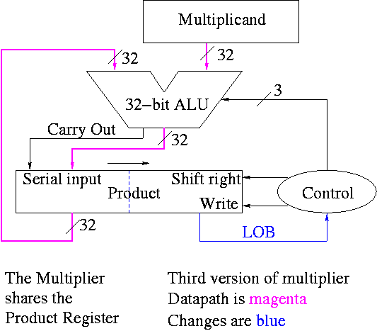
Control again boring.
- Send (ADD, 1) to (ALU, Product (shift right)).
- Send LOB to Product (write).
Redo the same example on the board.
The above was for unsigned 32-bit multiplication.
What about signed multiplication.
-
Save the signs of the multiplier and multiplicand.
-
Convert multiplier and multiplicand to non-neg numbers.
-
Use above algorithm.
-
Only use 31 steps not 32 since there are only 31 multiplier bits
(the HOB of the multiplier is the sign bit, not a bit used for
multiplying).
-
Compliment product if original signs were different.
There are faster multipliers, but we are not covering them.
4.7: Division
We are skiping division.
4.8: Floating Point
We are skiping floating point.
4.9: Real Stuff: Floating Point in the PowerPC and 80x86
We are skiping floating point.
Homework:
Read 4.10 ``Fallacies and Pitfalls'', 4.11 ``Conclusion'',
and 4.12 ``Historical Perspective''.
======== START LECTURE #13
========
MIDTERM EXAM
======== START LECTURE #14
========
Allan Gottlieb