================ Start Lecture #21
================
Chapter 5: Input/Output
5.1: Principles of I/O Hardware
5.1.1: I/O Devices
- Not much to say. Devices are varied.
- Block versus character devices:
- Devices, such as disks and CDROMs, with addressable chunks
(sectors in this case) are called block
devices,
These devices support seeking.
- Devices, such as Ethernet and modem connections, that are a
stream of characters are called character
devices.
These devices do not support seeking.
- Some cases, like tapes, are not so clear.
5.1.2: Device Controllers
These are the ``devices'' as far as the OS is concerned. That
is, the OS code is written with the controller spec in hand not with
the device spec.
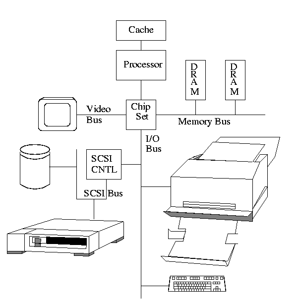
The figure in the book is so oversimplified as to be borderline
false. The following picture is closer to the truth (but really there
are several I/O buses of different speeds).

- The controller abstracts away some of the low level features of
the device.
- For disks, the controller does error checking and buffering.
- (Unofficial) In the old days it handled interleaving of sectors.
(Sectors are interleaved if the
controller or CPU cannot handle the data rate and would otherwise have
to wait a full revolution. This is not a concern with modern systems
since the electronics have increased in speed faster than the
devices.)
- For analog monitors (CRTs) the controller does
a great deal. Analog video is far from a bunch of ones and
zeros.
- Controllers are also called adaptors.
Using a controller
Think of a disk controller and a read request. The goal is to copy
data from the disk to some portion of the central memory. How do we
do this?
- The controller contains a microprocessor and memory and is
connected to the disk (by a cable).
- When the controller asks the disk to read a sector, the contents
come to the controller via the cable and are stored by the controller
in its memory.
- The question is how does the OS, which is running on another
processor, let the controller know that a disk read is desired and how
is the data eventually moved from the controller's memory to the
general system memory.
- Typically the interface the OS sees consists of some device
registers located on the controller.
- These are memory locations into which the OS writes
information such as sector to access, read vs. write, length,
where in system memory to put the data (for a read) or from where
to take the data (for a write).
- There is also typically a device register that acts as a
``go button''.
- There are also devices registers that the OS reads, such as
status of the controller, errors found, etc.
- So now the question is how does the OS read and write the device
register.
- With Memory-mapped I/O the device registers
appear as normal memory. All that is needed is to know at which
address each device regester appears. Then the OS uses normal
load and store instructions to write the registers.
- (Unofficial) Some systems instead have a special ``I/O space''
into which
the registers are mapped and require the use of special I/O space
instructions to accomplish the load and store. From a conceptual
point of view there is no difference between the two models.
Homework: 2
5.1.3: Direct Memory Access (DMA)

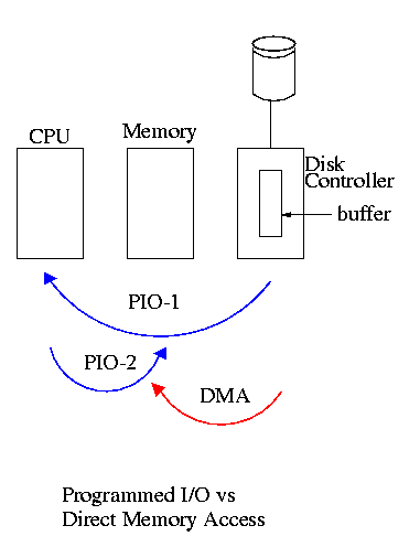
- With or without DMA, the disk controller pulls the desired data
from the disk to its buffer (and pushes data from the buffer to the
disk).
- Without DMA, i.e., with programmed I/O (PIO), the
cpu then does loads and stores (or I/O instructions) to copy the data
from the buffer to the desired memory location.
- With a DMA controller, the controller writes the memory without
intervention of the CPU.
- Clearly DMA saves CPU work. But this might not be important if
the CPU is limited by the memory or by system buses.
- Very important is that there is less data movement so the buses
are used less and the entire operation takes less time.
- Since PIO is pure software it is easier to change, which is an
advantage.
- DMA does need a number of bus transfers from the CPU to the
controller to specify the DMA. So DMA is most effective for large
transfers where the setup is amortized.
- Why have the buffer? Why not just go from the disk straight to
the memory.
Answer: Speed matching. The disk supplies data at a fixed rate, which might
exceed the rate the memory can accept it. In particular the memory
might be busy servicing a request from the processor or from another
DMA controller.
Homework: 5
5.2: Principles of I/O Software
As with any large software system, good design and layering is
important.
5.2.1: Goals of the I/O Software
Device independence
We want to have most of the OS, unaware of the characteristics of
the specific devices attached to the system. Indeed we also want the
OS to be largely unaware of the CPU type itself.
Due to this device independence, programs are
written to read and write generic devices and then at run time
specific devices are assigned. Writing to a disk has differences from
writing to a terminal, but Unix cp and DOS copy do not see these
differences. Indeed, most of the OS, including the file system code,
is unaware of whether the device is a floppy or hard disk.
Uniform naming
Recall that we discussed the value
of the name space implemented by file systems. There is no dependence
between the name of the file and the device on which it is stored. So
a file called IAmStoredOnAHardDisk might well be stored on a floppy disk.
Error handling
There are several aspects to error handling including: detection,
correction (if possible) and reporting.
- Detection should be done as close to where the error occurred as
possible before more damage is done (fault containment). This is not
trivial.
- Correction is sometimes easy, for example ECC memory does this
automatically (but the OS wants to know about the error so that it can
schedule replacement of the faulty chips before unrecoverable double
errors occur).
Other easy cases include successful retries for failed ethernet
transmissions. In this example, while logging is appropriate, it is
quite reasonable for no action to be taken.
- Error reporting tends to be awful. The trouble is that the error
occurs at a low level but by the time it is reported the
context is lost. Unix/Linux in particular is horrible in this area.
Creating the illusion of synchronous I/O
- I/O must be asynchronous for good performance. That is
the OS cannot simply wait for an I/O to complete. Instead, it
proceeds with other activities and responds to the notification when
the I/O has finished.
- Users (mostly) want no part of this. The code sequence
Read X
Y <-- X+1
Print Y
should print a value one greater than that read. But if the
assignment is performed before the read completes, the wrong value is
assigned.
- Performance junkies sometimes do want the asynchrony so that they
can have another portion of their program executed while the I/O is
underway. That is they implement a mini-scheduler in their
application code.

Sharable vs dedicated devices
For devices like printers and tape drives, only one user at a time
is permitted. These are called serially reusable
devices, and are studied next chapter.
Devices like disks and Ethernet ports can be shared by processes
running concurrently.
Layering
Layers of abstraction as usual prove to be effective. Most systems
are believed to use the following layers (but for many systems, the OS
code is not available for inspection).
- User level I/O routines.
- Device independent I/O software.
- Device drivers.
- Interrupt handlers.
We give a bottom up explanation.
5.2.2: Interrupt Handlers
We discussed an interrupt handler before when studying page faults.
Then it was called ``assembly language code''.
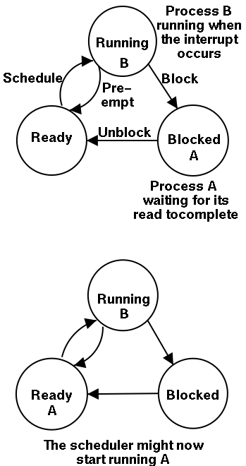
In the present case, we have a process blocked on I/O and the I/O
event has just completed. So the goal is to make the process ready.
Possible methods are.
- Releasing a semaphore on which the process is waiting.
- Sending a message to the process.
- Inserting the process table entry onto the ready list.
Once the process is ready, it is up to the scheduler to decide when
it should run.
5.2.3: Device Drivers
The portion of the OS that ``knows'' the characteristics of the
controller.
The driver has two ``parts'' corresponding to its two access
points. Recall the following figure from the beginning of the course.

- Accessed by the main line OS via the envelope in response to an I/O
system call. The portion of the driver accessed in this way is
sometimes call the ``top'' part.
- Accessed by the interrupt handler when the I/O completes (this
completion is signaled by an interrupt). The portion of the driver
accessed in this way is sometimes call the ``bottom'' part.
Tanenbaum describes the actions of the driver assuming it is
implemented as a process (which he recommends). I give both that view
point and the self-service paradigm in which the driver is invoked by
the OS acting in behalf of a user process (more precisely the process
shifts into kernel mode).


