Now we need the main control.
So 9 bits.
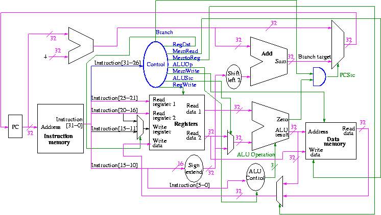
The following figure shows where these occur.
They all are determined by the opcode
The MIPS instruction set is fairly regular. Most fields we need are always in the same place in the instruction.
| MemRead: | Memory delivers the value stored at the specified addr |
| MemWrite: | Memory stores the specified value at the specified addr |
| ALUSrc: | Second ALU operand comes from (reg-file / sign-ext-immediate) |
| RegDst: | Number of reg to write comes from the (rt / rd) field |
| RegWrite: | Reg-file stores the specified value in the specified register |
| PCSrc: | New PC is Old PC+4 / Branch target |
| MemtoReg: | Value written in reg-file comes from (alu / mem) |
We have seen the wiring before (and have a hardcopy to handout).
We are interested in four opcodes.
Do a stage play
add r9,r5,r1 r9=r5+r1   0   5   1   9   0  32
sub r9,r9,r6            0   9   6   9   0  34
beq r9,r0,-8            4   9   0   <  -2   >
slt r1,r9,r0            0   9   0   1   0  42
lw  r1,102(r2)         35   2   1   <  100  >
sw  r9,102(r2)
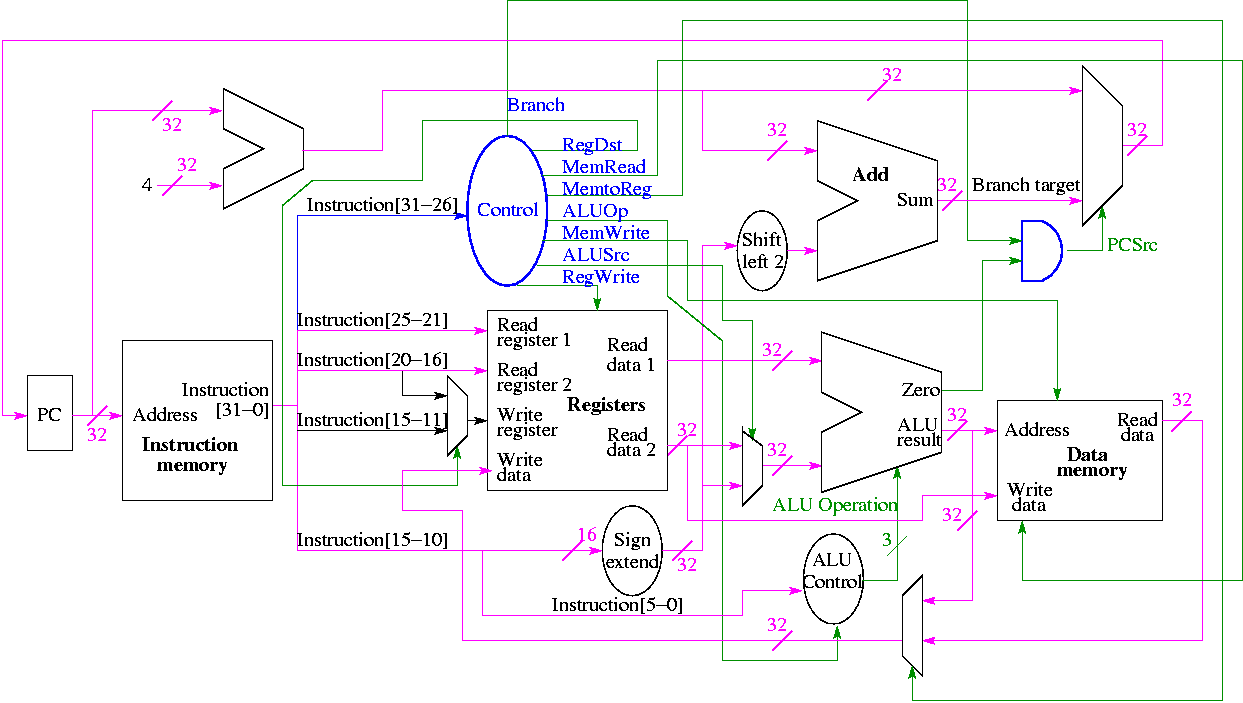
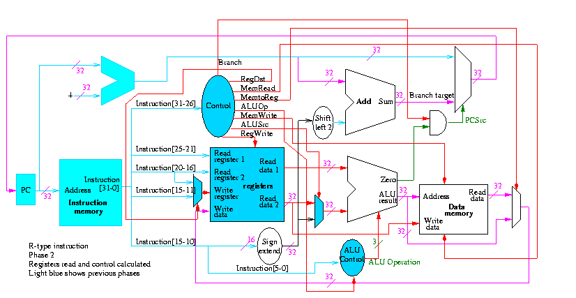
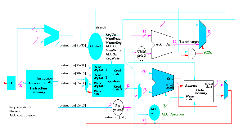
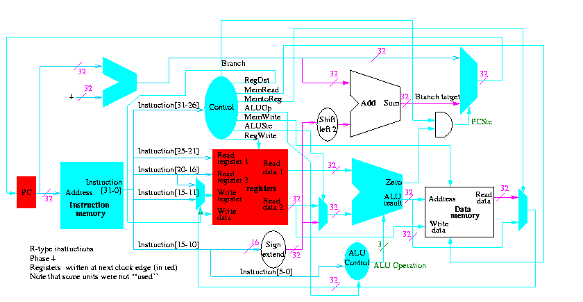
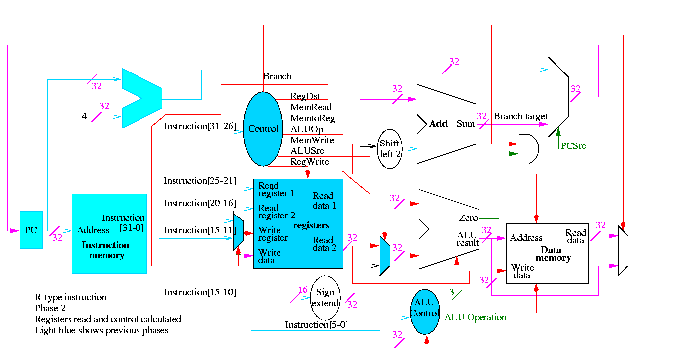
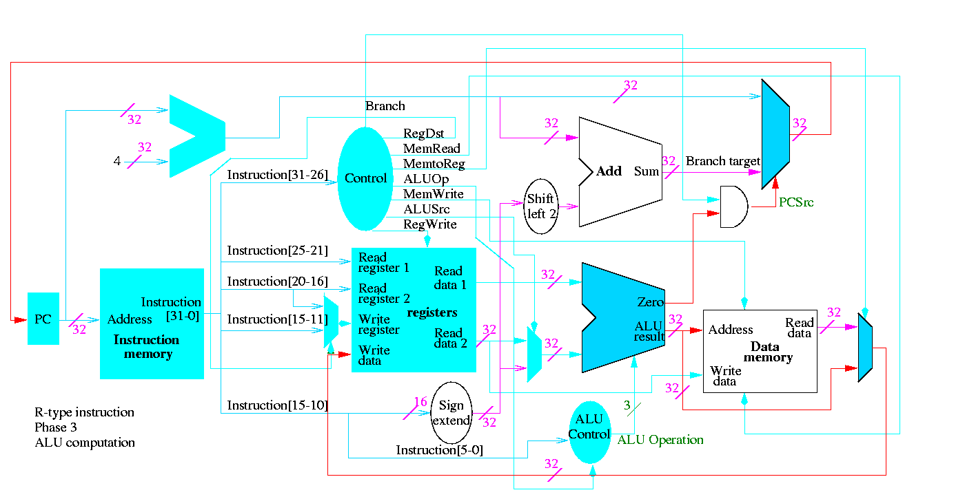
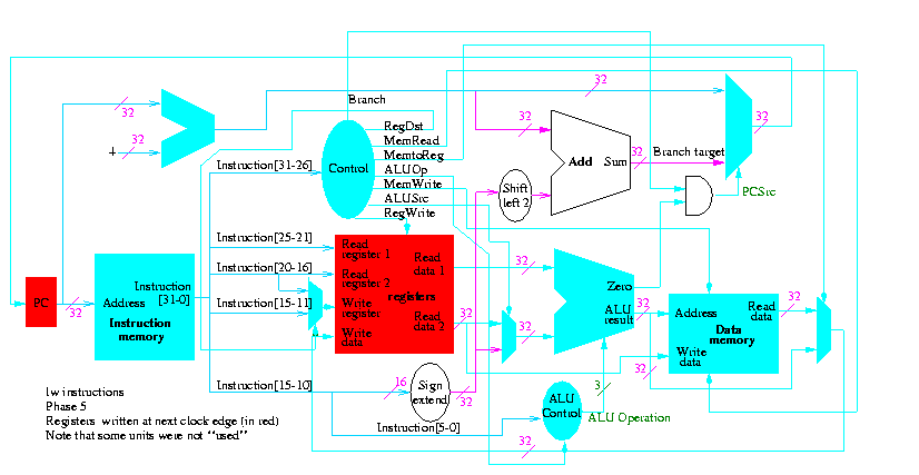
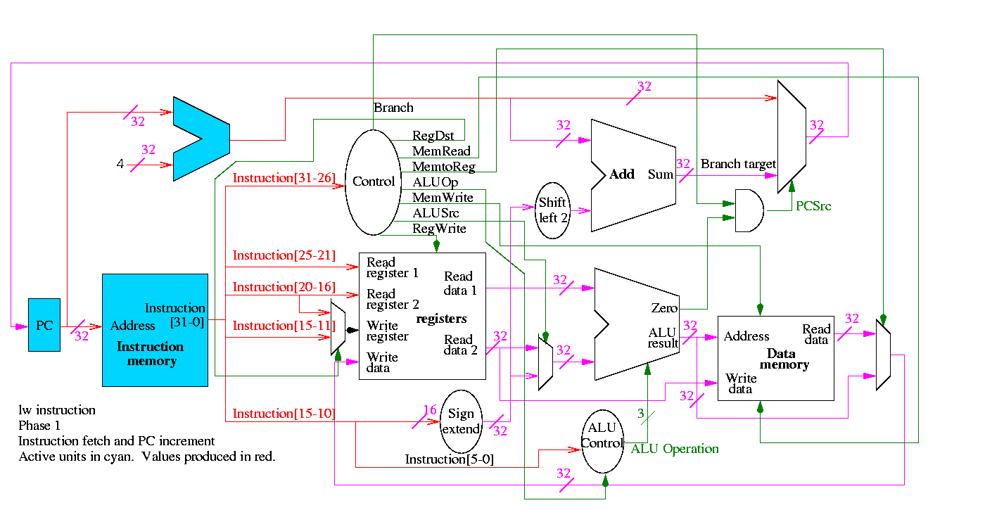
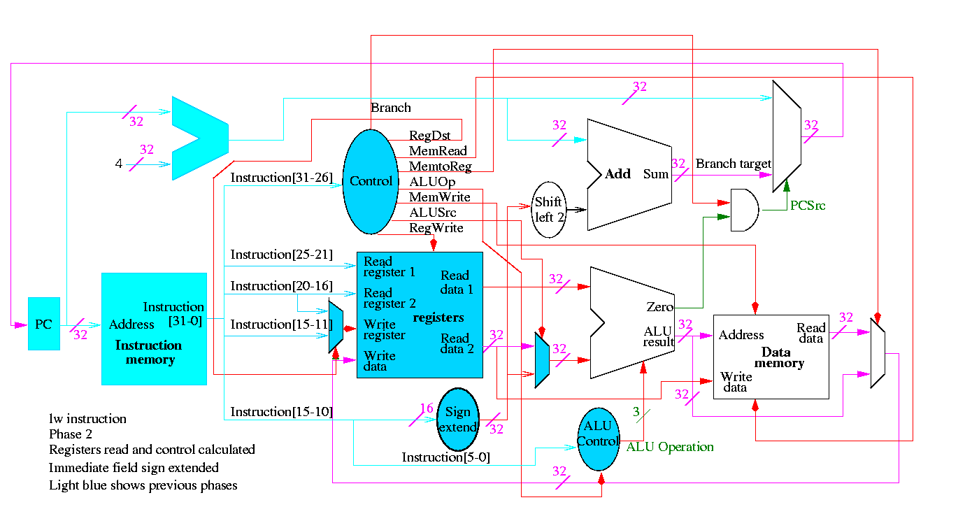
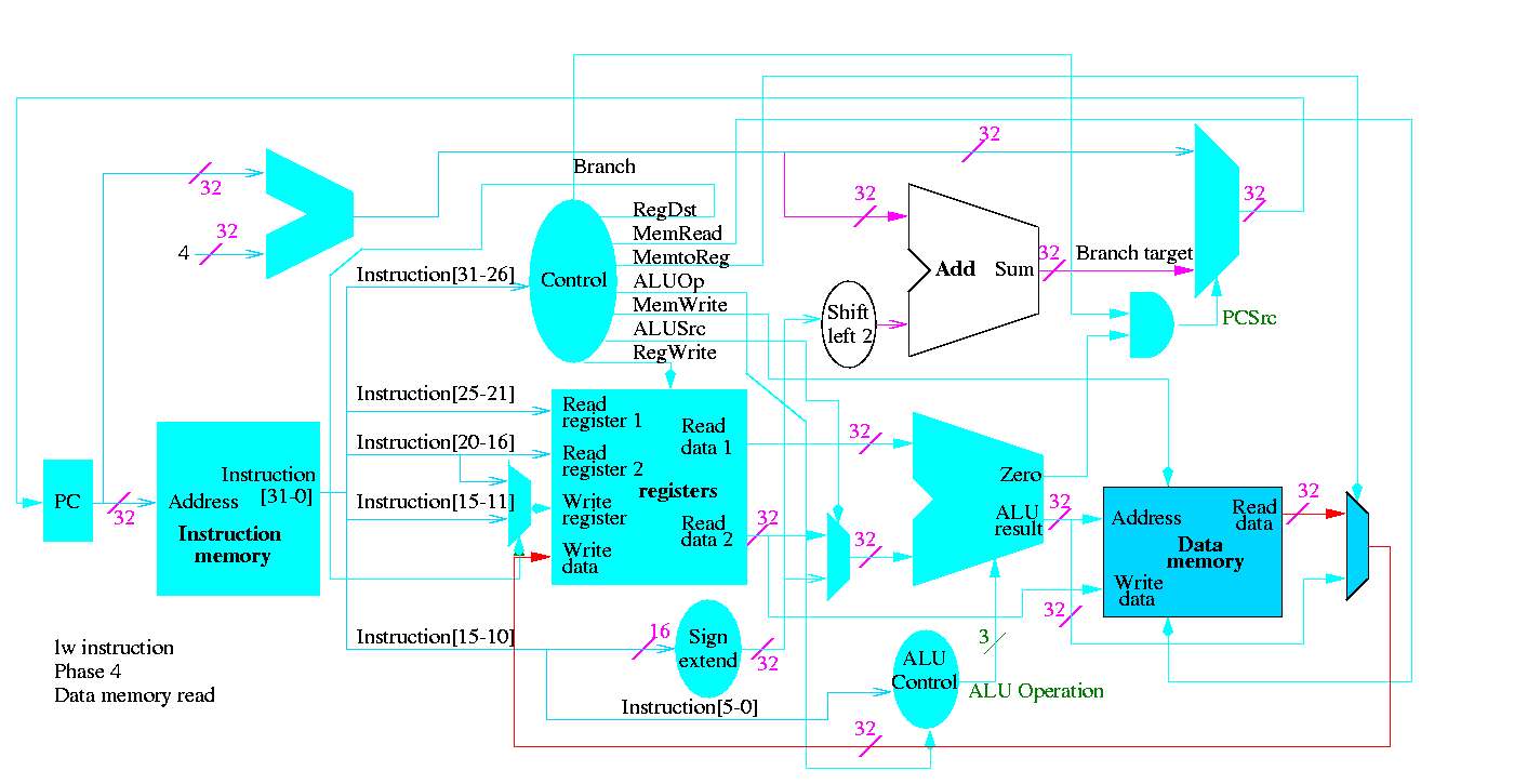
The following figures illustrate the play.
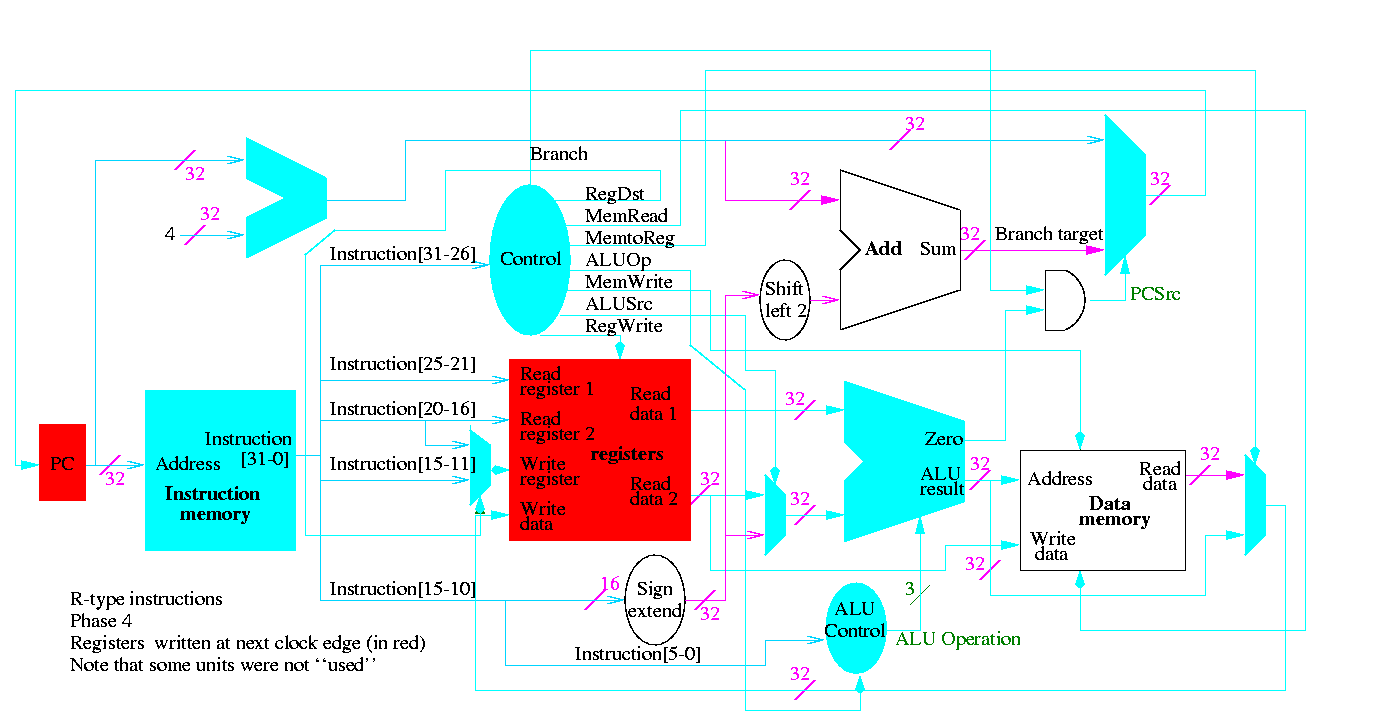
We start with R-type instructions


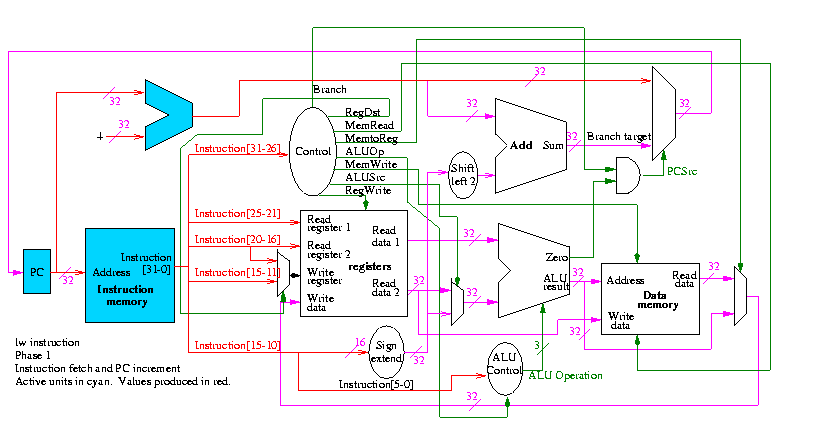
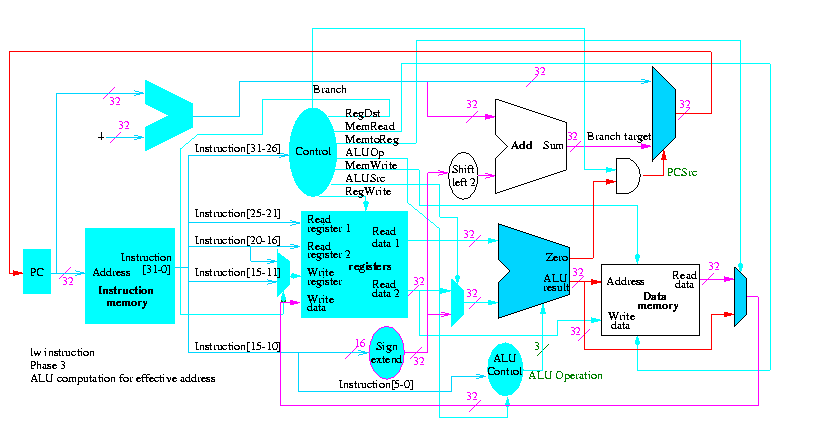
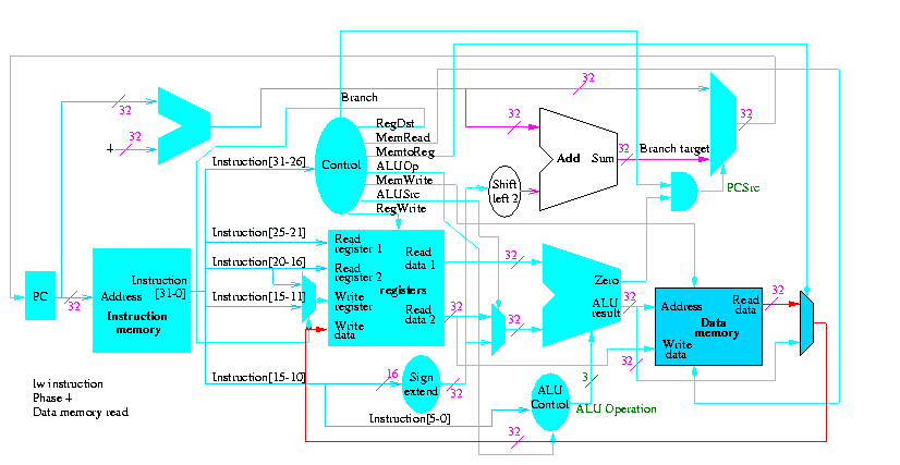
Next we show lw


The following truth table shows the settings for the control lines for each opcode. This is drawn differently since the labels of what should be the columns are long (e.g. RegWrite) and it is easier to have long labels for rows.
| Signal | R-type | lw | sw | beq |
|---|---|---|---|---|
| Op5 | 0 | 1 | 1 | 0 |
| Op4 | 0 | 0 | 0 | 0 |
| Op3 | 0 | 0 | 1 | 0 |
| Op2 | 0 | 0 | 0 | 1 |
| Op1 | 0 | 1 | 1 | 0 |
| Op0 | 0 | 1 | 1 | 0 |
| RegDst | 1 | 0 | X | X |
| ALUSrc | 0 | 1 | 1 | 0 |
| MemtoReg | 0 | 1 | X | X |
| RegWrite | 1 | 1 | 0 | 0 |
| MemRead | 0 | 1 | 0 | 0 |
| MemWrite | 0 | 0 | 1 | 0 |
| Branch | 0 | 0 | 0 | 1 |
| ALUOp1 | 1 | 0 | 0 | 0 |
| ALUOp | 0 | 0 | 0 | 1 |
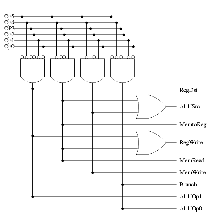
Now it is straightforward but tedious to get the logic equations
When drawn in pla style the circuit is