- For demand paging, the case is pretty clear. Every implementation I know of allocates a frame for the page miss and fetches the page from disk. That is it does both an allocate and a fetch.
- For caching this is not always the case. Since there are two
optional actions there are four possibilities.
- Don't allocate and don't fetch: This is sometimes called write around. It is done when the data is not expected to be read and is large.
- Don't allocate but do fetch: Impossible, where would you put the fetched block?
- Do allocate, but don't fetch: Sometimes called no-fetch-on-write. Also called SANF (store-allocate-no-fetch). Requires multiple valid bits per block since the just-written word is valid but the others are not (since we updated the tag to correspond to the just-written word).
- Do allocate and do fetch: The normal case we have been using.
Chapter 8: Interfacing Processors and Peripherals.
With processor speed increasing 50% / year, I/O must improved or essentially all jobs will be I/O bound.

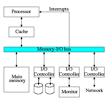
The diagram on the right is quite oversimplified for modern PCs but serves the purpose of this course.
8.2: I/O Devices
Devices are quite varied and their datarates vary enormously.
- Some devices like keyboards and mice have tiny datarates.
- Printers, etc have moderate datarates.
- Disks and fast networks have high rates.
- A good graphics card and monitor has huge datarate
Show a real disk opened up and illustrate the components
- Platter
- Surface
- Head
- Track
- Sector
- Cylinder
- Seek time
- Rotational latency
- Transfer time
8.4: Buses
A bus is a shared communication link, using one set of wires to connect many subsystems.
- Sounds simple (once you have tri-state drivers) ...
- ... but it's not.
- Very serious electrical considerations (e.g. signals reflecting
from the end of the bus. We have ignored (and will continue to
ignore) all electrical issues.
- Getting high speed buses is state-of-the-art engineering.
- Tri-state drivers:
- A output device that can either
- Drive the line to 1
- Drive the line to 0
- Not drive the line at all (be in a high impedance state)
- Can have many of these devices devices connected to the same wire providing careful to be sure that all but one are in the high-impedance mode.
- This is why a single bus can have many output devices attached (but only one actually performing output at a given time).
- A output device that can either
- Buses support bidirectional transfer, sometimes using separate
wires for each direction, sometimes not.
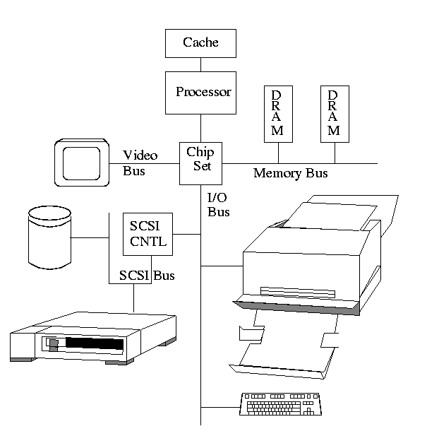
- Normally the memory bus is kept separate from the I/O bus. It is
a fast synchronous bus and I/O devices can't keep
up.
- Indeed the memory bus is normally custom designed (i.e., companies
design their own).
- The graphics bus is also kept separate in modern designs for
bandwidth reasons, but is an industry standard (the so called AGP
bus).
- Many I/O buses are industry standards (ISA, EISA, SCSI, PCI) and
support open architectures, where components can
be purchased from a variety of vendors.


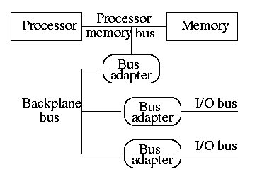
- This figure above is similar to H&P's figure 8.9(c), which is
shown on the right. The primary difference is that they have the
processor directly connected to the memory with a processor memory
bus.
- The processor memory bus has the highest bandwidth, the backplane
bus less and the I/O buses the least. Clearly the (sustained)
bandwidth of each I/O bus is limited by the backplane bus.
Why?
Because all the data passing on an I/O bus must also pass on the backplane bus. Similarly the backplane bus clearly has at least the bandwidth of an I/O bus.
- Bus adaptors are used as interfaces between buses. They perform
speed matching and may also perform buffering, data width
matching, converting between synchronous and
asynchronous buses.
- For a realistic example draw, on the board the diagram from
Microprocessor Reports on the new Intel chip set. I am
not sure of copyright questions so will not put it in the
notes.
- Bus adaptors have a variety of names, e.g. host adapters, hubs,
bridges.
- Bus lines (i.e. wires) include those for data (data lines),
function codes, device addresses. Data and address are considered
data and the function codes are considered control (remember our
datapath for MIPS).
- Address and data may be multiplexed on the same lines (i.e., first
send one then the other) or may be given separate lines. One is
cheaper (good) and the other has higher performance (also
good). Which is which?
Ans: the multiplexed version is cheaper.
Synchronous vs. Asynchronous Buses
A synchronous bus is clocked.
- One of the lines in the bus is a clock that serves as the clock
for all the devices on the bus.
- All the bus actions are done on fixed clock cycles. For example,
4 cycles after receiving a request, the memory delivers the first
word.
- This can be handled by a simple finite state machine (FSM).
Basically, once the request is seen everything works one clock at
a time. There are no decisions like the ones we will see for an
asynchronous bus.
- Because the protocol is so simple it requires few gates and is
very fast. So far so good.
- Two problems with synchronous buses.
- All the devices must run at the same speed.
- The bus must be short due to clock skew
- Processor to memory buses are now normally synchronous.
- The number of devices on the bus are small
- The bus is small
- The devices (i.e. processor and memory) are prepared to run at the same speed
- High speed is needed
An asynchronous bus is not clocked.
- Since the bus is not clocked a variety of devices can be on the
same bus.
- There is no problem with clock skew (since there is no clock).
- But the bus must now contain control lines to coordinate
transmission.
- Common is a handshaking protocol.
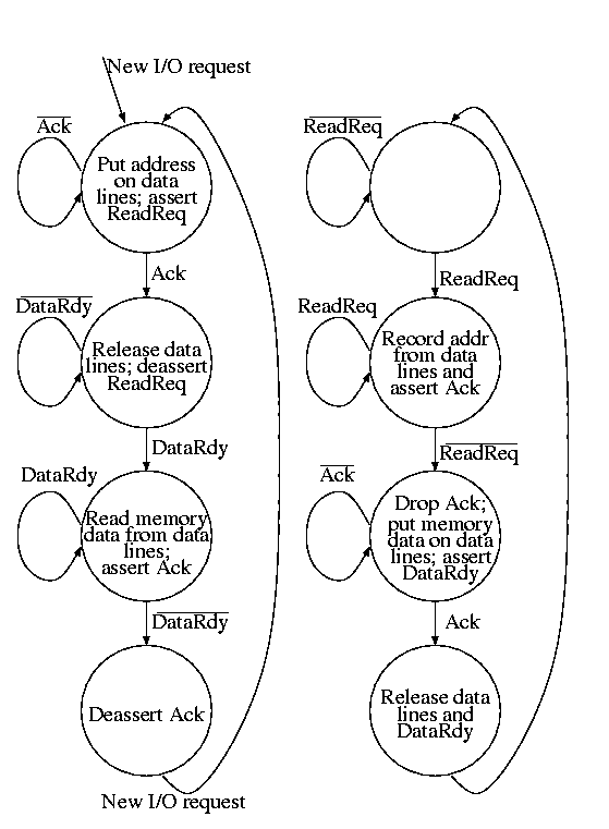
- We now show a protocol in words and FSM for a device to obtain data from memory.

- The device makes a request (asserts ReadReq and puts the
desired address on the data lines).
- Memory, which has been waiting, sees ReadReq, records the
address and asserts Ack.
- The device waits for the Ack; once seen, it drops the
data lines and deasserts ReadReq.
- The memory waits for the request line to drop. Then it can drop
Ack (which it knows the device has now seen). The memory now at its
leasure puts the data on the data lines (which it knows the device is
not driving) and then asserts DataRdy. (DataRdy has been deasserted
until now).
- The device has been waiting for DataRdy. It detects DataRdy and
records the data. It then asserts Ack indicating that the data has
been read.
- The memory sees Ack and then deasserts DataRdy and releases the
data lines.
- The device seeing DataRdy low deasserts Ack ending the show.