======== START LECTURE #15
========
Lab 2. Due in three weeks. Modify lab 1 to deal with sub, slt, zero detect,
overflow. Also lab 2 is to be 32 bits. That is, Figure 4.18.
Go over the exam.
Chapter 5: The processor: datapath and control
Homework:
Start Reading Chapter 5.
5.1: Introduction
We are going to build the MIPS processor
Figure 5.1 redrawn below shows the main idea

Note that the instruction gives the three register numbers as well
as an immediate value to be added.
- No instruction actually does all this
- We have datapaths for all possibilities
- Will see how we arrange for only certain datapaths to be used for
each instruction type
- For example R type uses all three registers but not the
immediate field
- The I type uses the immediate but not all three registers
- The memory address for a load or store is the sum of a register
and an immediate
- The data value to be stored comes from a register
5.2: Building a datapath
Let's begin doing the pieces in more detail.
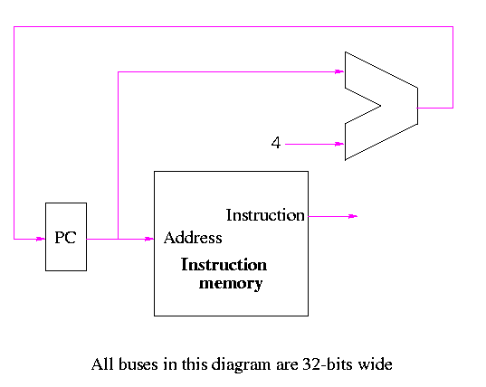
Instruction fetch
We are ignoring branches for now.

- How come no write line for the PC register?
- Ans: We write it every cycle.
- How come no control for the ALU
- Ans: This one always adds
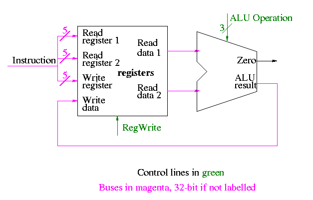
R-type instructions

- ``Read'' and ``Write'' in the diagram are adjectives not verbs.
- The 32-bit bus with the instruction is divided into three 5-bit
buses for each register number (plus other wires not shown).
- Two read ports and one write port, just as we learned in chapter 4
- The 3-bit control consists of Bnegate and Op from chapter 4


