======== START LECTURE #12
========
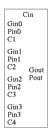
As noted just above the tall skinny box is useful for all size
CLAs. To expand on that point and to review CLAs, let's redo CLAs with
the general box.
Since we are doing 4-bits at a time, the box takes 9=2*4+1 input bits
and produces 6=4+2 outputs
A 4-bit adder is now
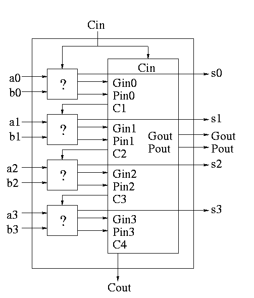
What does the ``?'' box do?
- Calculates Gi and Pi based on ai and bi
- Calculate s1 based on ai, bi, and Ci=Cin (normal full adder)
- Do not bother calculating Cout
Now take four of these 4-bit adders and use the identical
CLA box to get a 16-bit adder
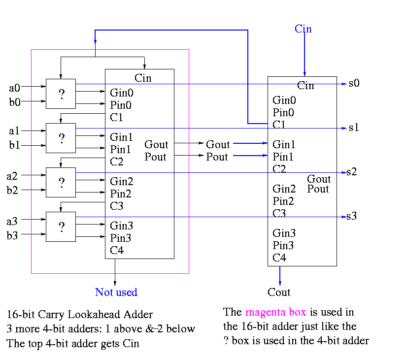
Four of these 16-bit adders with the identical
CLA box to gives a 64-bit adder.
Shifter
-
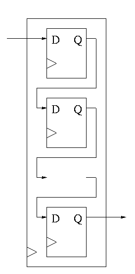
Just a string of D-flops; output of one is input of next
-
Input to first is the serial input.
-
Output of last is the serial output.
-
We want more.
-
Left and right shifting (with serial input/output)
-
Parallel load
-
Parallel Output
-
Don't shift every cycle
-
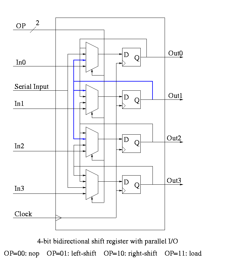
Parallel output is just wires.
-
Shifter has 4 modes (left-shift, right-shift, nop, load) so
-
4-1 mux inside
-
2 control lines must come in
-
We could modify our registers to be shifters (bigger mux), but ...
-
Our shifters are slow for big shifts; ``barrel shifters'' are better
Homework:
A 4-bit shift register initially contains 1101. It is
shifted six times to the right with the serial input being
101101. What is the contents of the register after each
shift.
Homework:
Same register, same init condition. For
the first 6 cycles the opcodes are left, left, right, nop,
left, right and the serial input is 101101. The next cycle
the register is loaded (in parallel) with 1011. The final
6 cycles are the same as the first 6. What is the contents
of the register after each cycle?
Multipliers
-
Recall how to do multiplication.
-
Multiplicand times multiplier gives product
-
Multiply multiplicand by each digit of multiplier
-
Put the result in the correct column
-
Then add the partial products just produced
-
We will do it the same way ...
... but differently
-
We are doing binary arithmetic so each ``digit'' of the
multiplier is 1 or zero.
-
Hence ``multiplying'' the mulitplicand by a digit of the
multiplier means either
-
Getting the multiplicand
-
Getting zero
-
Use an ``if appropriate bit of multiplier is 1'' stmt
-
To get the ``appropriate bit''
-
Start with the LOB of the multiplier
-
Shift the multiplier right (so the next bit is the LOB)
-
Putting in the correct column means putting it one column
further left that the last time.
-
This is done by shifting the
multiplicand left one bit each time (even if the multiplier
bit is zero)
-
Instead of adding partial products at end, keep a running sum
-
If the multiplier bit is zero add the (shifted)
multiplicand to the running sum
-
If the bit is zero, simply skip the addition.
-
This results in the following algorithm
    product <- 0
    for i = 0 to 31
        if LOB of multiplier = 1
            product = product + multiplicand
        shift multiplicand left 1 bit
        shift multiplier right 1 bit
Do on board 4-bit addition (8-bit registers) 1100 x 1101
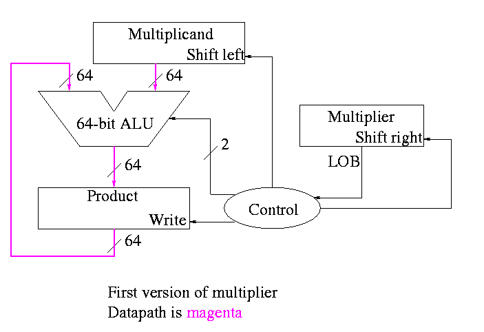
What about the control?
-
Always give the ALU the ADD operation
-
Always send a 1 to the multiplicand to shift left
-
Always send a 1 to the multiplier to shift right
-
Pretty boring so far but
-
Send a 1 to write line in product if and only if
LOB multiplier is a 1
-
I.e. send LOB to write line
-
I.e. it really is pretty boring
