======== START LECTURE #10
========
> I have a question about the first lab; I'm not sure how we
> would implement a mux, would a series of if-else
> statements be an acceptable option?

No.  But that is a good question.  if-then-elif...-else
would be a FUNCTIONAL simulation.  That is you are
simulating what the mux does but not HOW it does it.  For a
gate level simulation, you need to implement the mux in
terms of AND, NOT, OR, XOR and then write code link
Fulladder.c

The implementation of a two way mux in terms of AND OR NOT
is figure B.4 on page B-9 of the text.  You need to do a 3
way mux.
Homework:
(for fun) prove this last statement (4.29)
addu, subu, addiu
These add and subtract the same the same was as add and sub,
but do not signal overflow
4.4: Logical Operations
Shifts: sll, srl
- R type, with shamt used and rs not used
- sll $1,$2,5
reg2 gets reg1 shifted left 5 bits
- Why do we need both sll and srl,
i.e, why not just have one of them and use a negative
shift amt for the other?
Ans: The shift amt is only 5 bits and need shifts from 0 to 31
bits. Hence not enough bits for negative shifts.
- Op is 0 (these are ALU ops, will understand why in a few weeks).
Bitwise AND and OR: and, or, andi, ori
No surprises.
- and $r1,$r2,$r3
or $r1,$r2,$r3
- standard R-type instruction
- andi $r1,$r2,100
ori $r1,$r2,100
- standard I-type
4.5: Constructing an ALU--the fun begins
First goal is 32-bit AND, OR, and addition
Recall we know how to build a full adder. Will draw it as
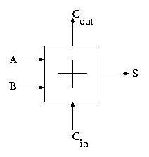
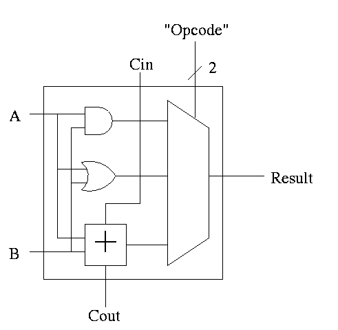
With this adder, the ALU is easy.
- Just choose the correct operation (ADD, AND, OR)
- Note the principle that if you want a logic box that sometimes
computes X and sometimes computes Y, what you do is
- Compute X and also compute Y
- Put both X and Y into a mux
- Use the ``sometimes'' condition as the select line to the mux
32-bit version is simple.
- Use an array of logic elements for the logic. The logic element
is the 1-bit ALU
- Use buses for A, B, and Result.
- ``Broadcast'' Opcode to all of the internal 1-bit ALUs. This
means wire the external Opcode to the Opcode input of each of the
internal 1-bit ALUs
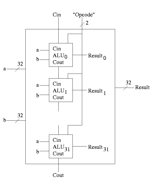
First goal accomplished.
How about subtraction?
- Big deal about 2's compliment is that
A - B = A + (2's comp B) = A + (B' + 1)
- Get B' from an inverter (naturally)
- Get +1 from the CarryIn
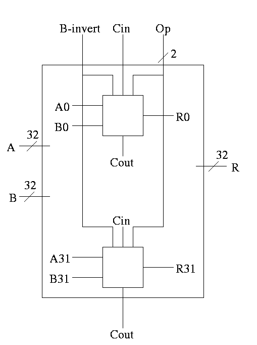
1-bit ALU with ADD, SUB, AND, OR is

For subtraction set Binvert and Cin.
32-bit version is simply a bunch of these.
- For subtraction assert both B-invert and Cin.
- For addition de-assert both B-invert and Cin.
- For AND and OR d-assert B-invert. Cin is a don't care
Simulating Combinatorial Circuits at the Gate Level
Write a procedure for each logic box with the following properties.
- Parameters for each input and output
- (Local) variable for each (internal) wire
- Can only do AND OR XOR NOT
- In the C language & | ^ ~
- Other languages similar
- No conditional assignment; the output is a FUNCTION of the input
- Single assignment to each variable.
Multiple assignments would correspond to a cycle
- Bus (set of signals) represented by array
- Testing
- Exhaustive possible for 1-bit cases
- Cleverness for n-bit cases (n=32, say)
Handout: FullAdder.c
and FourBitAdder.c.
Lab 1: Do the equivalent for 1-bit-alu (without
subtraction). This is easy. Lab 2 will be similar but for a
more sophisticated ALU.
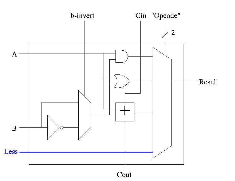
Extra requirements for MIPS alu:
-
slt set-less-than
-
Result reg is 1 if a < b
Result reg is 0 if a >= b
-
So need to set the LOB (low order bit, aka least significant bit)
of the result equal to the sign bit of a subtraction, and set the
rest of the result bits to zero.
-
Idea #1. Give the mux another input, called LESS.
This input is brought in from outside the bit cell.
That is, if the opcode is slt we make the select line to the
mux equal to 11 (three) so that the the output is the this new
input. For all the bits except the LOB, the LESS input is
zero. For the LOB we must figure out how to set LESS.
-
Idea #2. Bring out the result of the adder (BEFORE the mux)
Only needed for the HOB (high order bit, i.e. sign) Take this
new output from the HOB, call it SET and connect it to the
LESS input in idea #1 for the LOB. The LESS input for other
bits are set to zero.
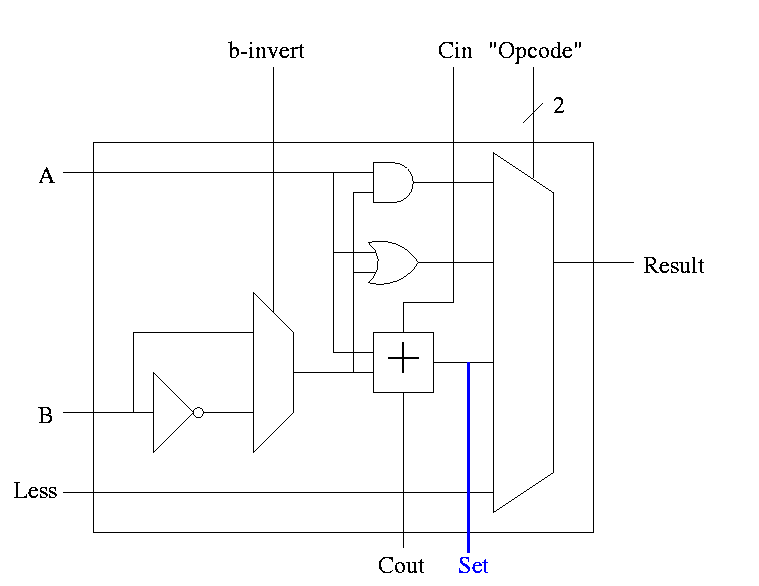
-
Why isn't this method used?
-
Ans: It is wrong!
-
Example using 3 bit numbers (i.e. -4 .. 3).
Try slt on -3 and +2.
True subtraction (-3 - +2) give -5.
The negative sign in -5 indicates (correctly) that -3 < +2.
But three bit subtraction -3 - +2 gives +3 ! Hence we will
incorrectly conclude that -3 is NOT less than +2.
(Really, it signals an overflow. unless doing unsigned)
-
Solution: Need the correct rule for less than (not just sign of
subtraction)
Homework: figure out correct rule, i.e. prob 4.23.
Hint: when an overflow occurs the sign bit is definitely wrong (so the
complement of the sign bit is right).
-
Overflows
- The HOB is already unique (outputs SET)
- Need to enhance it some more to produce the overflow output
- Recall that we gave the rule for overflow: you need to examine
- Whether add or sub (binvert)
- The sign of A
- The sign of B
- The sign of the result
- Since this is the HOB we have all the sign bits.
- The book also uses Cout, but this appears to be an error
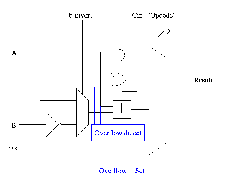
-
Simpler overflow detection
- An overflow occurs if and only if the carry in to the HOB
differs from the carry of of the HOB
-
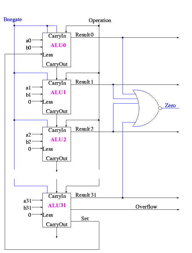
Zero Detect
- To see if all bits are zero just need NOR of all the bits
- Conceptually trivially but does require some wiring
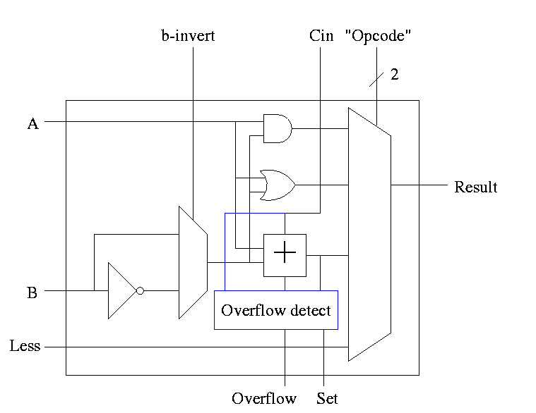
-
Observation: The initial Cin and Binvert are always
the same. So just use one input called Bnegate.
The Final Result is
Symbol for the alu is
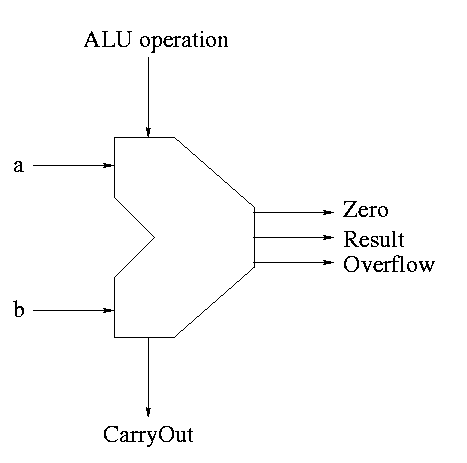
What are the control lines?
-
Bnegate (1 bit)
-
OP (2 bits)
What functions can we perform?
-
and
-
or
-
add
-
sub
-
set on less than
What (3-bit) values for the control lines do we need for each function?
| and | 0 | 00 |
| or | 0 | 01 |
| add | 0 | 10 |
| sub | 1 | 10 |
| slt | 1 | 11 |