======== START LECTURE #5
========
B.4: Clocks

Frequency and period
- Hertz (Hz), Megahertz, Gigahertz vs. Seconds, Microseconds,
Nanoseconds
- Old (descriptive) name for Hz is cycles per second (CPS)
- Rate vs. Time
Edges
- Rising Edge; falling edge
- We use edge-triggered logic
- State changes occur only on a clock edge
- Will explain later what this really means
- One edge is called the Active edge
- The edge (rising or falling) on which changes occur
- Choice is technology dependent
- Sometimes trigger on both edges (e.g., RAMBUS memory)
Synchronous system
Now we are going to add state elements to the combinational
circuits we have been using previously.
Remember that a combinational/combinatorial circuits has its outpus
determined by its input, i.e. combinatorial circuits do not contain
state.
Reading and writing State Elements.
State elements include state (naturally).
- i.e., memory
- state-elements have clock as an input
- can change state only at active edge
- produce output Always; based on current state
- all signals that are written to state elements must be valid at
the time of the active edge.
- For example, if cycle time is 10ns make sure combinational circuit
used to compute new state values completes in 10ns
- So state elements change on active edge, comb circuit
stablizes between active edges.
- Can have loops like this.
- Think of registers or memory as state elements.
- A loop like the above is a cycle of the computer
B.5: Memory Elements
We want edge-triggered clocked memory and will only use
edge-triggered clocked memory in our designs. However we get
there by stages. We first show how to build unclocked
memory; then using unclocked memory we build
level-sensitive clocked memory; finally from
level-sensitive clocked memory we build edge-triggered
clocked memory.
Unclocked Memory

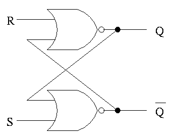
S-R latch (set-reset)
- ``Cross-coupled'' nor gates
- Don't assert both S and R at once
- When S is asserted (i.e., S=1 and R=0)
- the latch is Set (that's why it is called S)
- Q becomes true (Q is the output of the latch)
- Q' becomes false (Q' is the complemented output)
- When R is asserted
- the latch is Reset
- Q becomes false
- Q' becomes true
- When neither one is asserted
- The latch remains the same, i.e. Q and Q' stay as they
were
- This is the memory aspect
Clocked Memory: Flip-flops and latches
The S-R latch defined above is not clocked memory. Unfortunately the
terminology is not perfect.
For both flip-flops and
latches the output equals the value stored in the
structure. Both have an input and an output (and the complemented
output) and a clock input as well. The clock determines when the
internal value is set to the current input. For a latch, the change
occurs whenever the clock is asserted (level sensitive). For a
flip-flop, the change only occurs during the active edge.
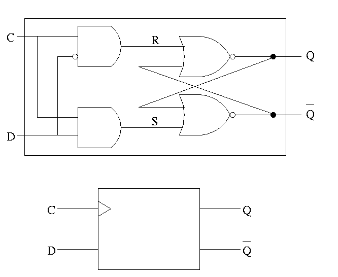
D latch
The D is for data

- The left part uses the clock.
- When the clock is low, both R and S are forced low
- When the clock is high, S=D and R=D' so the value store is D
- Output changes when input changes and the clock is asserted
- Level sensitive rather than edge triggered
- Sometimes called a transparent latch
- We won't use these in designs
- The right part is the S-R (unclocked) latch we just did
In the traces below notice how the output follows the input when the
clock is high and remains constant when the clock is low. We assume
the stored value is initially low.

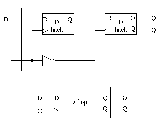
D or Master-Slave Flip-flop

This was our goal. We now have an edge-triggered, clocked memory.
- Built from D latches, which are transparent
- The result is Not transparent
-
- Changes on the active edge
- This one has the falling edge as active edge
- Sometimes called a master-slave flip-flop
- Note substructures with letters reused
having different meaning (block structure a la algol)
- Master latch (the left one) is set during the time clock is
asserted.
Remember that the latch is transparent, i.e. follows
its input when its clock is asserted. But the second
latch is ignoring its input at this time. When the
clock falls, the 2nd latch pays attention and the
first latch keeps producing whatever D was at
fall-time.
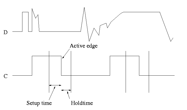
- Actually D must remain constant for some time around
the active edge.
- The set-up time before the edge
- The hold time after the edge
- See diagram below

Note how much less wiggly the output is with the master-slave flop
than before with the transparent latch. As before we are assuming the
output is initially low.
Homework:
Try moving the inverter to the other latch
What has changed?

This picture shows the setup and hold times discussed above. It is
crucial when building circuits with flip flops that D is stable during
the interval between the setup and hold times. Note that D is wild
outside the critical interval, but that is OK.
Homework:
B.18


