Start Lecture #4
Remark: Show in class how to broadcast S (select line) to many ANDs (used for wide muxes in 2nd lab) and assign lab 2.
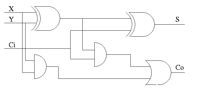
Now we include the carry-in.
the total number of 1s in X, Y, and Ci is odd
Homework:
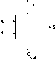
We have implemented 1-bit versions of AND (a basic gate), OR (a
basic gate), and SUM (the FA just constructed, which we henceforth
draw as shown on the right).
We now want a single structure that, given another input (the
desired operation, another one of those
control lines
), produces as output the specified operation.
There is a general principle used to produce a structure that yields either X or Y depending on the value of operation.
This mux, with an operation select line, gives a structure
that sometimes
produces one result and sometimes
produces another.
Internally both results are always
produced.
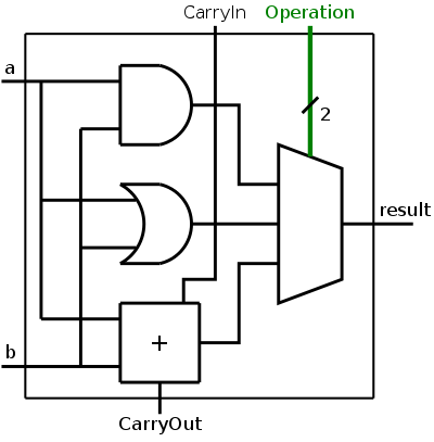
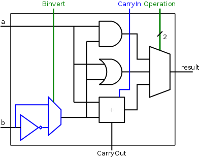
In our case we have three possible operations so we need a three way mux and the select line is a 2-bit wide bus. With a 2-bit select line we can specify 4 operations, for now we are using only three.
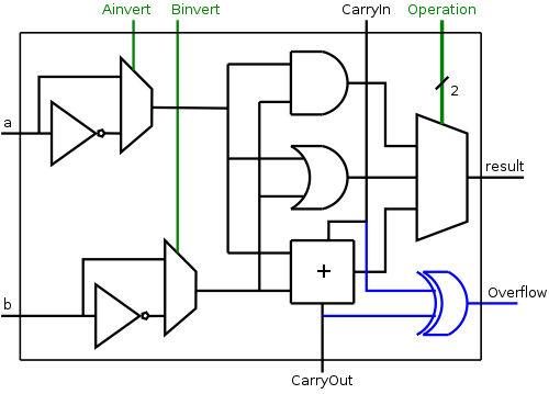
We show the diagram for this 1-bit ALU on the right.
The Operation
input is shown in green to distinguish it as a
control line rather than a data line.
That is, the goal is to produce two bits of result from 2 (AND, OR)
or 3 (ADD) bits of data.
The 2 bits of control tell what to do, rather than what data to do
it on.
The extra data output (CarryOut) is always produced. Presumably if the operation was AND or OR, CarryOut is not used.
I believe the distinction between data and control will become quite clear as we encounter more examples. However, I wouldn't want to be challenged to give a (mathematically precise) definition.
A 1-bit ALU is interesting, but we need a 32-bit ALU to implement the MIPS 32-bit operations, acting on 32-bit data values.
For AND and OR, there is almost nothing to do; a 32-bit AND is just 32 1-bit ANDs so we can simply use an array of logic elements.
However, ADD is a little more interesting since the bits are not quite independent: The CarryOut of one bit becomes the CarryIn of the next.
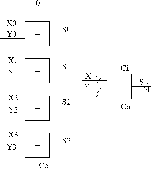
Let's start with a 4-bit adder.
How about a 32-bit adder, or even an an n-bit adder ?
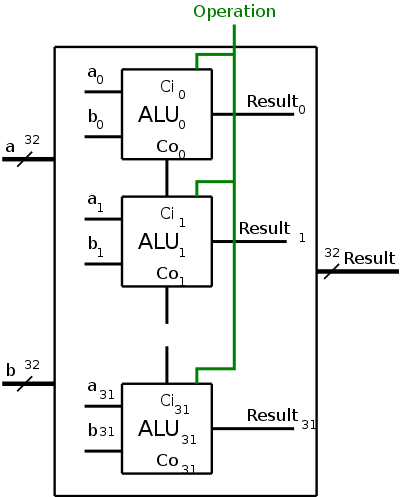
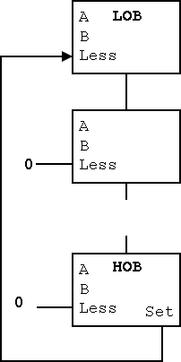
To obtain a 32-bit ALU, we put together the 1-bit ALUs in a manner similar to the way we constructed a 32-bit adder from 32 FAs. Specifically we proceed as follows and as shown in the figure on the right.
BroadcastOperation to all of the internal 1-bit ALUs. This means wire the external Operation to the Operation input of each of the internal 1-bit ALUs.
Remark
This is one place were the our treatment
must go a little out of order.
Appendix B in the book assumes you have read the chapter on computer
arithmetic; in particular it assumes that you know about two's
complement arithmetic.
I do not assume you know this material and we will cover it
later, when we do that chapter.
What I will do here is assert some facts about two's complement
arithmetic that we will use to implement the circuit for SUB.
End of Remark.
For simplicity I will be presenting 4-bit arithmetic. We are really interested in 32-bit arithmetic, but the idea is the same and the 4-bit examples are much shorter (and hence less likely to contain typos).
With 4 bits, there can be only 16 numbers. One of them is zero, 8 are negative, and 7 are positive.
The high order bit (hob) on the left is the sign bit. The sign bit is zero for positive numbers and for the number zero; the sign bit is one for negative numbers.
Zero is written simply 0000.
1-7 are written 0001, 0010, 0011, 0100, 0101, 0110, 0111. That is, you set the sign bit zero and write 1-7 using the remaining three lob's. This last statement is also true for zero.
-1, -2, ..., -7 are written by taking the two's complement of the corresponding positive number. The two's complement is computed in two steps.
If you take the two's complement of -1, -2, ..., -7, you get back the corresponding positive number. Try it.
If you take the two's complement of zero you get zero. Try it.
What about the 8th negative number?
-8 is written 1000.
But if you take its (4-bit) two's complement,
you must get the wrong number because the correct
number (+8) cannot be expressed in 4-bit two's complement notation.
Amazingly easy (if you ignore overflows).
No change is needed to our circuit above to handle two's complement numbers for AND/OR/ADD. That statement is not clear for ADD and will be shown true later in the course.
We wish to augment the ALU so that we can perform subtraction as well. As we stated above, A-B is obtained by taking the two's complement of B and adding. A 1-bit implementation is drawn on the right with the new structures in blue (I often use blue for this purpose). The enhancement consists of
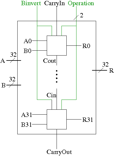
A 32-bit version is simply a bunch of the 1-bit structures wired together as shown on the right.
AND, OR, AND, and SUB are found in nearly all ALUs. In that sense, the construction up to this point has been generic. However, most real architectures have some extras. For MIPS they include.
Set on less than(slt), not common and not so easy.
We noted above that our ALU already gives us the ability to
calculate AB', a fairly uncommon logic function.
A MIPS ALU needs NOR and, by DeMorgan's law,
A NOR B = (A + B)' = A'B',
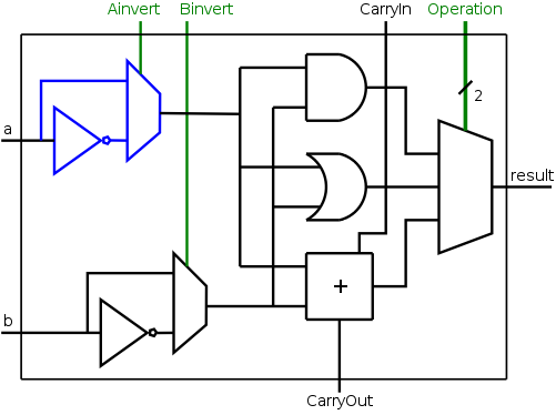
which is rather close, we just need to invert A as well as B.
The diagram on the right shows the needed structures: an inverter to get A', a mux to choose between A and A', and a control line for the mux.
NOR is obtained by asserting Ainvert and Binvert and setting Operation=00.
The other operations are done as before, with Ainvert de-asserted.
The 32-bit version is a straightforward ...
Homework: Draw the 32-bit ALU that supports AND, OR, ADD, SUB, and NOR.
Remark: As with two's complement arithmetic, I just present the bare boned facts here; they are explained later in the course.
The facts are trivial (although the explanation is not). Indeed there is just one fact.
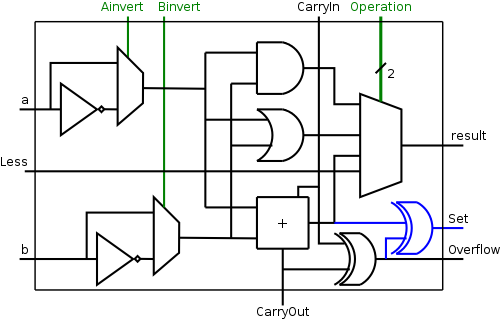
Only the hob portion of the ALU needs to be changed. We need to see if the carry-in is different from the carry-out, but that is exactly XOR. The simple modification to the hob structure is shown on the right.
Do on the board 4-bit twos complement addition of
The 32-bit version is again a straightforward ...
Homework: Draw the 32-bit ALU that supports AND, OR, ADD, SUB, and NOR and that asserts an overflow line when appropriate.
We are given two 32-bit, two's complement numbers A and B as input and seek a 32-bit result that is 1 if A<B and 0 otherwise. Note that only the lob of the result varies; the other bits are all 0.
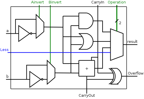
The implementation is fairly clever as we shall see.
The problem with the above solution is that it ignores overflows. Consider the following 4-bit (instead of 32-bit) example.
The fix is to use the correct rule for less than rather than the
sometimes incorrect rule the sign bit of A-B is 1
.
Homework: figure out correct rule, i.e. a non-pictorial version of problem B.24. Hint: When an overflow occurs, the sign bit is definitely wrong.
The diagram on the right shows the correct calculation of Set.